This page as an PDF-Document? Click on that Symbol and wait a little moment... ---> |
 |
|

FlightCtrl V3.0 |
.jpg?m=1453719653 "http://gallery3.mikrokopter.de/var/albums/intern/MK-Baugruppen/FlightCtrl/FlightCtrl-V3.0/FC_V3_(350).jpg?m=1453719653")
Inhaltsverzeichnis
Info / Download
The new FlightCtrl V3.0 combines the flight control system and the 32-bit navigation one board.
All features you can use are described here: Features
(optional accessory is required)
The FlightCtrl V3.0 is include:
- Cable to connect a PPM sum signal receiver
- Telemetry connection
- Tiny Servo Adatper for connecting servos (e.g. for camera gimbals)
- Already installed software
- fully functional and tested.
INFO:
You can use the FlightCtrl V3.0 only with MikroKopter software from version V2.14!
Additionally needed is a GPS and an external compass.
Shoplink : Flight-Ctrl V3.0
Shoplink : GPS incl. ext. Kompass
Aktuelle Software : Download
Technical data

- Weight: 26g
Dimensions: 67mm x 67mm (Hole distance: 44,6mm x 44,6mm => compatible with the old FlightCtrl)
- Voltage: up to 7S (30V)
- 32-bit technology
- 3 switching outputs
- Status displays for each switching outputs
- Up to 6 servo outputs
- Altitude control (up to 5000m)
- CAM Trigger-Input (to connect with a hot shoe of the camera)
- Redundant use of motor control
Redundant flight control system (with second FlightCtrl V3.0)
- Possibility to connect different receiver systems
- Store the LOG data on SD card
- ...
Connections
Molex front
|
MAIN |
CAM |
Servo |
IO2 |

Connecting power supply + buzzer
With the Molex connector MAIN the Flight Ctrl V3.0 is supplied with voltage (Lipo voltage).
Also the BL-Ctrl and the buzzer are provided with this port.

Connection
- 5pol Molexkabel
FlightCtrl -> MAIN
BL-Ctrl Verteiler -> FlightCtrl.
- Buzzer
Contact Speaker +/- on your BL-Ctrl board
Connection CAM

The connection "C / CAM" is a switching output. Here you can connect a shuttercable to trigger e.g. a camera.
At this contact you have 5V (max. 100mA) and GND. 5V is still there, GND is switched.
The switching output is optionally also available at the pads C and 5V next to it.
These are connected parallel to the molex contacts CAM.
The settings for this switching output can be done in the KopterTool under Output (Output1).
Connection SERVO

At the connection Servo you can connect the external servo PCB TinyPCB (Shoplink).
Via the plug connector on the TinyPCB you have 2 servo outputs (Servo1+2) where you can connect 2 Servos. Here you can connect e.g. a camera mount. The plug connector includes 5V (max. 1A) of the FlightCtrl V3.0.

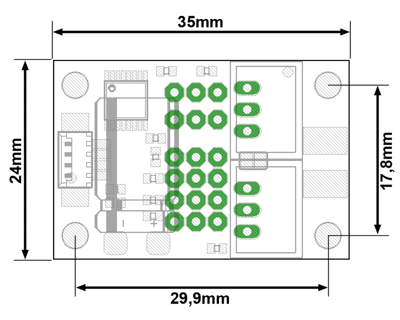
At the connection Servo you can also connect the optional board ServoPCB (Shoplink). Here you have up to 6 servo outputs. The ServoPCB includes 2 Recoms to power up the servos (max. 5V / 2A). For this you have to connect the board with the Lipo power of the BL-Ctrl board.
The dimensions of ServoPCB can be found here: Maße
Connection IO2

At the connection IO2, the optional Hot-shoe adapter (Link) can be connected.
Across the Hot-shoe adapter the triggering of the camera will be detected.
In an extra .txt file (on the SD card in the FlightCtrl V3.0) the exact triggering and the GPS position will recorded.
Info:
If the Hot-shoe adapter is not in use, the triggering of CAM is recorded in the LOG file.
Info:
The Hot-shoe adapter will NOT trigger the camera !!!
To trigger the camera you need a Shuttercable.
Molex right
|
IO1 |
Analog |
EXT2 |
UART2 |
I2C |

Anschluss IO1

IO1 can be used for the function "Parachute".
If the contact is closed, immediately every motor is switched off.
To use the feature, a license is required.
Connection I2C
 ]
]
The connection I2C is for external boards like our new CamCtrl.
With this board you can control Sony foto- and video cameras. Here you can e.g. trigger, REC on/off or zoom the camera.
And you can see the telemetry (e.g. REC on/off, number of pictures etc.) of the CamCtrl in your Graupner HoTT transmitter or via the KopterTool.
Molex rear
|
CAN |
CAN |
UART (Update) |
SD CARD |
|

Connection CAN

The connection CAN is needed if you will connect 2 FlightCtrl V3.0 for a redundant use.
INFO: Here we need only one of the two connections. The second parallel one is optional to use.
Connection UART (Update)

At the connection UART (Update) you can use MK-USB V3 (Shoplink). You need the MK-USB e.g. to update the software, change the settings or to send waypoint lists to the copter.
INFO:
The supply of the FlightCtrl must always be done by an external power source (LiPo).
The jumper on the MK-USB V3 has no function.
SD CARD

In the FlightCtrl V3.0 you can use a microSD card. This micro SD card can have max. 2GB and must be formatted with FAT16.
Here we store all flights incl. the telemetry data. With the KopterTool you can download then the LOG files.
To open the LOG files and take a look on it you can use the GPXViewer.
Molex left
|
BL |
BL |
GPS |
Compass |
EXT1 |

Connection BL
If you use a second FlightCtrl V3.0 to have it redundant, you can connect the UART socket of the BL-Ctrl V3 board with the BL socket of the Slave FlightCtrl.
When you use e.g. a single Okto BL-Ctrl V3 board, you connect only one of the BL sockets of the Slave FlightCtrl with the UART of the BL board.
When you use e.g. a Double Quadro V3 board, you need both BL connections of the Slave FlightCtrl to connect the UART of the upper and the lower BL board.
Connection GPS

Via the connection GPS the 5-pin Molex cable is connected to the MK-GPS.
Connection Compass

Anschluss Ext. Kompass

Anschluss Kompass MKGPS
Via the connection Compass the 4-pin Molex cable is connected to the external compass.
Connection EXT1 / L

The connection "EXT1" is a switching output. Here you can connect e.g. a shuttercable to trigger e.g. a camera or a ExtensionPCB to switch LEDs or something else.
At this molex contact you have 5V (max. 100mA) and GND. 5V is still there, GND is switched.
You can find this switching output also on the pads L and 5V beside the connection "EXT1".
These pads are connected parallel to the connection "EXT1".
The settings for this switching output can be done in the KopterTool under Output (Output2).
Important:
Do NOT connect LEDs directly! You can destroy this output!
If you will switch LEDs please use e.g. the ExtensionPCB.
Pads bottom

The solder pads at the bottom of the FlightCtrl V3.0 are normally not in use. Only if you have to connect a special receiver or if there is no other way to connect it via the molex connection you can use it.
5V/GND/R/T
Connection for receiver (see Receiver connections)
Telemetry
activates the telemetry output to the pad "Telem." for Graupner HoTT or Jeti.
(Default: close)
Slave
Set the FlightCtrl as Master or Slave => Master = open / Slave = close.
(Default: open)
Batt
Connection for power supply (up to 7S (30V))
(the FlightCtrl is normally to power up via the molex cable on "MAIN")
C/D
I2C connection for BL-Ctrl
(the BL-Ctrl are normally connected via themolex cable on "MAIN")
GND/AD4
- not in use
PC4
- not in use
Pads serial

In addition to the connector UART (Update) you have this serial input/output also on this 10 pads. When you will use it you have to solder a 10-pin header.
If needed you can connect here a Wi.232, a Bluetooth or the old MK-USB.
INFO:
The connection UART (Update) and the serial pads are connected parallel. It can be used only one connection at the same time.
NMEA
Via the serial port of the FlightCtrl V3 we can also send GPS data in NMEA format.
the records RMC and GGA are sent with 57600 Baud via PIN9 (TxD) and PIN7 (GND). << BR >>
To send NMEA data via the serial output you have to setup the "SETTINGS.INI" on your microSD card.
You can edit the SETTINGS.INI on your microSD card with an editor.
Under NMEA_INTERVAL you can set then the transmission interval (e.g. "500" => 500ms = 0,5s).
Under Baudrate for PC-UART you can change transmission speed if needed (e.g. "576" for 57600 Baud or "96" for 9600 Baud).
Further information can be found here: NMEA
LEDs - status message
Via the LEDs on the FlightCtrl V3.0 different status messages can be detected.
LED Status |
||||
NC |
FC |
event |
||
|
||||
|
|
|
|
No power supply |
|
|
|
|
Supply voltage is present, everything OK |
|
|
|
|
no or wrong receiver is connected or transmitter is switched off |
|
|
|
|
Wrong mixer is set or Compass is not calibrated or magnet error or ... |
|
|
|
|
Software deleted on the NaviCtrl (e.g. after improper update) |
|
|
|
|
Software deleted on the FlightCtrl (e.g. after improper update) |
|
||||
CAM / EXT1 / EXT2 |
event |
|||
|
switching output not active / not switched |
|||
|
switching output active / switched |
|||
|
||||
|
||||


Receiver connections
Please make sure that the correct receiver is set under "Channels".
Connection receiver |
|||
|
|||
PPM-Sum signal receiver |
|
||
Pad |
Function |
cable color |
|
Telem. |
n/a |
n/a |
|
|
|||
Graupner HoTT |
|
||
Pad |
Function |
cable color |
|
Telem. |
Telemetry connection |
gray |
|
|
|||
Jeti |
|
||
Pad |
Function |
cable color |
|
Telem. |
Telemetry connection |
gray |
|
|
|||
Spektrum satellite receiver |
|
||
Pad |
Function |
cable color |
|
GND |
GND |
black |
|
|
|||
Futaba S.Bus Empfänger |
|
||
Pad |
Function |
cable color |
|
5V |
+5V |
red |
|


Software Update
INFO: The FlightCtrl V3.0 is supplied with current software and is already tested and functional.
If there is a newer software version then the one on the FlightCtrl V3.0 you can update the FlightCtrl V3.0 quick and easy.
The FlightCtrl V3.0 consists of two parts (flight control system and navigation). Here we need then 2parts of software and the right KopterTool:
Program => Kopter_Tool_Vx_xxx.zip
Software flight control system=> Flight-Ctrl_MEGA1284p_Vx_xxx.hex
Software navigation=> Navi-Ctrl_STR9_Vx_xxx.hex
(x_xxx => version numbers)
It is importand that all 3 parts have the same versionsnumber! The letter at the end can be arbitrary.
Download
The latest software for the FlightCtrl V3.0 can be downloaded here:

Step 1: unpack file

The downloaded file is a compressed file with the name Software_MikroKopter.zip.
In this compressed file you'll find the necessary software and the matching KopterTool.
The easiest way is to unpack the software and the KopterTool to the desktop.
To do this make a double klick on the .zip file with the left mouse button. Move then the needed files via "drag & drop" to your desktop.
Step 2: open KopterTool

Open the folder KopterTool_Vx_xxx (x_xxx = version number) and start the program MikroKopter-Tool.exe.
If you open the program for the first time, you have to confirm the license conditions. Then you see the KopterTool window.
A "click" on the button Firmware update & Terminal will open the terminal window.
Info:
The copter must be connected with your computer and the fully charged battery is connected with your copter.
The transmitter is ON.
Step 3: Software update

Important:
During the update do NOT disconnect the connection between copter and computer. The battery on your copter must be fully charged.
In the terminal window you can start now the update:
Click on the button Update Software (serial)...
In the software window choose Flight-Ctrl_MEGA1284p_Vx_XXx.hex
Click on the button Open => update starts
Now you see the installing of the new software in the terminal window in green letters.
Wait until the update is done (white letters).
To start the second part of the update do again:
Click on the button Update Software (serial)...
In the software window choose Navi-Ctrl_STR9_Vx_xxx.hex
lick on the button Open => update starts
Now you see the installing of the new software in the terminal window in green letters.
Wait until the update is done (white letters).
After the update is done, click on the button to MK-Tool... to go back to the main window.
There you can check the versions numbers.
(with the button NaviCtrl and FlightCtrl you can change the display)
After an update you have to check the functions before you fly.
Update error

If something went wrong during the update, the software on the FlightCtrl V3.0 can be deleted. In that case you can mean that there is no connection and nothing works.
But do not panic. You can install the software quick and easy again.
This will help to install the software:
- The copter is:
connected via MK-USB with your computer (do NOT use a wireless connection!)
- the battery is fully charged and connected with your copter
- The terminal window is open and the right COM port is set
If you start the update you can see maybe now a TIMEOUT
Now we do this:
- Start the update again
If there is no OK after 3-4 dots (behind "(try to reset Hardware....)" ->
- open the battery connection and directly
- close the battery connection
Now you should have an OK behind the dots and the update should go further
Info:
If the update will not run, check the COM port and the connections.
If there is no way to update the FlightCtrl V3.0 again, please contact the MikroKopter support: support@hisystems.de
Settings
To use the copter with your transmitter you have to set the channels in your transmitter and in the settings for the FlightCtrl V3.0.
You can now set this channels manually and individually.
Or you use the ready setup file MK-Setting_(Vx.xx).mkp that you also find in the .zip file.
(see: Software Update - ''Software_!MikroKopter.zip'')
A matching model memory for Graupner HoTT transmitter can be downloaded here: HoTT Sender
Step 1: unpack setting memory

In the downloaded software package you will find the required setting file MK-Setting_(Vx.xx).mkp.
Open the .zip file again and move the needed files via "drag & drop" to your desktop. .
Step 2: import the settings

Now you can import the unzipped file MK-Setting_(Vx.xx).mkp in your copter. Do now as described:
Open the KopterTool
Click the button Settings... => the settings open
Below click the button Load...
Select the file MK-Setting_(Vx.xx).mkp
Confirm with the button Open
- In the settings window you can now see the channel settings
Write this settings now in your copter with a click on the button Write
INFO: The copter has 5 Parametersets (Settings). This you can set individually.
It is advisable to save these settings on all 5 Parametersets. If you now change inadvertently the setting
(via your transmitter) you have still the same functions.
To do this change only the number of the Parameterset and save each single number with a click on the button Write.
At the end click the button OK to leave this menu.
Others
- The bootloader of the FC3.0 is not public and can not be read
Never use a ISP programmer to upgrade the FlightCtrl. This can clear the Bootloader.
If you have damage your FlightCtrl V3.0 please contact the Support of HiSystems: support@hisystems.de