|
Größe: 10664
Kommentar:
|
Größe: 11995
Kommentar:
|
| Gelöschter Text ist auf diese Art markiert. | Hinzugefügter Text ist auf diese Art markiert. |
| Zeile 4: | Zeile 4: |
| ||<tablewidth="300px" tablestyle="text-align: center;"#ffffa0> {{http://mikrokopter.de/images/deu.gif}} Seite in [[Sender|Deutsch]] || | ||<tablewidth="520px" tablestyle="text-align: center;"bgcolor="#ffffa0"> {{http://mikrokopter.de/images/deu.gif}} Seite in [[Sender|deutsch]] ||<bgcolor="#ffffa0"> {{http://mikrokopter.de/images/fra.gif}} Page en [[fr/Sender|français]] || |
| Zeile 9: | Zeile 9: |
| = Generelles = Grundsätzlich kann jeder Sender mit mehr als vier Kanälen für den MikroKopter genutzt werden.<<BR>> Nur der Empfänger muss ein PPM Summensignal liefern können. Dies wird von der FlightCtrl benötigt.<<BR>> Ein normaler Empfänger mit Servoausgängen kann nicht angeschlossen werden!<<BR>> Sollte es zu dem eigenen Sender keinen passenden Empfänger mit PPM Summensignal geben, kann ein vorhandener Empfänger allerdings umgerüstet werden. Hierzu wird das [[https://www.mikrocontroller.com/index.php?main_page=product_info&cPath=76&products_id=551|QuadroPPM12]] benötigt. Dies wird an die Servoausgänge des Empfängers angeschlossen und erzeugt hieraus ein PPM Summensignal.<<BR>><<BR>> |
= general = Basically, each transmitter with more than four channels can be used for MikroKopter.<<BR>> Only the receiver must provide a PPM sum signal. This is required by the FlightCtrl.<<BR>> A normal receiver with servo outputs can '''not''' be connected!<<BR>> If there is no receiver with a PPM sum signal for your transmitter, you can use a [[https://www.mikrocontroller.com/index.php?main_page=product_info&cPath=76&products_id=551|QuadroPPM12]]. This can be connected to the receiver output and generating a PPM composite signal.<<BR>><<BR>> |
| Zeile 12: | Zeile 15: |
| == wieviel Kanäle == Die ersten vier Kanäle werden für die Steuerung des Kopters benötigt. Die Kanäle sind wie folgt voreingestellt: |
The range between the transmitter and receiver depends on the used transmitter / receiver. For more detailed information of the range please ask the manufacturer.<<BR>> For the greatest possible range, the receiver shall not be shielded or covered mounted.<<BR>><<BR>> |
| Zeile 15: | Zeile 18: |
| * Kanal 1 = Gas * Kanal 2 = Roll * Kanal 3 = Nick * Kanal 4 = Gier |
== how much channels == The first four channels are needed for the control of the Kopter. The channels are preset as follows: |
| Zeile 20: | Zeile 21: |
| Je nachdem wieviel Kanäle der Sender bietet, können weitere Funktionen genutzt werden.<<BR>> Für jede Funktion wie z.B. das Halten der Höhe, die GPS Funktionen "PositionHold" und "ComingHome", "CareFree", das neigen der Kamerahalterung und weitere Funktionen wird ein zusätzlicher Kanal benötigt.<<BR>> |
* Channel 1 = Throttle * Channel 2 = Roll * Channel 3 = Nick * Channel 4 = Yaw Depending on how many channels offered by the transmitter, further functions can be used.<<BR>> For each function, such as for example keeping the height, the GPS functions "PositionHold" and "ComingHome", "CareFree", the nick of the camera mount and other functions, required an additional channel.<<BR>> |
| Zeile 24: | Zeile 30: |
| Es gibt vier verschiedene Bedienmöglichkeiten bei Sendern. Diese nennen sich Mode1, Mode2, Mode3 und Mode4.<<BR>> Die verschiedenen "Mode" bestimmen welche Funktion Gas (Throttle), Gier (Yaw), Nick, Roll) mit welchem Stick des Senders genutzt wird.<<BR>><<BR>> | There are four different control options for transmitter. They are called Mode1, Mode2, Mode3 and Mode4.<<BR>> These four "Mode" have different throttle, yaw, pitch, roll.<<BR>><<BR>> |
| Zeile 26: | Zeile 33: |
| Am einfachsten ist der Kopter mit Mode2 zu steuern. Vor allem, wenn noch keine Erfahrungen im Modellflug vorhanden sind.<<BR>> Hierbei ist auf dem linken Stick Gas (Throttle) und Gier (Yaw) und auf dem rechten Stick Nick und Roll.<<BR>> {{http://gallery.mikrokopter.de/main.php?g2_view=core.DownloadItem&g2_itemId=75772&g2_serialNumber=1}} <<BR>><<BR>> | '''To control the Kopter, the easiest way is Mode2. Especially if you don't have experience in aircraft model before.'''<<BR>><<BR>> |
| Zeile 28: | Zeile 35: |
| Wer schon seit längerem mit einer anderen Belegung fliegt, kann natürlich auch diese beibehalten.<<BR>> [[http://gallery.mikrokopter.de/main.php/v/tech/Sender-Mode1.jpg.html|{{http://gallery.mikrokopter.de/main.php?g2_view=core.DownloadItem&g2_itemId=75771|http://gallery.mikrokopter.de/main.php/v/tech/Sender-Mode1.jpg.html}}]] | On Mode2 throttle an yaw are on the left stick, nick and roll on the right stick.<<BR>><<BR>> Normally you can change the mode1-4 of the transmitter. How to change you will find in the manual of the transmitter<<BR>> {{http://gallery.mikrokopter.de/main.php?g2_view=core.DownloadItem&g2_itemId=75772&g2_serialNumber=1}} <<BR>><<BR>> If you are using also a different Mode, you can use it too.<<BR>> [[http://gallery.mikrokopter.de/main.php/v/tech/Sender-Mode1.jpg.html|{{http://gallery.mikrokopter.de/main.php?g2_view=core.DownloadItem&g2_itemId=75771|http://gallery.mikrokopter.de/main.php/v/tech/Sender-Mode1.jpg.html}}]] |
| Zeile 33: | Zeile 45: |
| * Throttle: please be sure the throttle is "non-neutralizing". If a clip is located at the Stick you have to remove it. More details you find on the manual of the transmitter. * Idle means throttle is down (to the pilot), full throttle corresponds to up or away from the pilot. * It is recommended that the gas "sliding", because the gas is very sensitive. |
|
| Zeile 34: | Zeile 49: |
| * Gas: Es sollte unbedingt der Gashebel auf "nicht neutralisierend" umbauen werden. Ist an diesem Stick eien Feher verbaut wird diese also entfernt. Näheres zum Umbau verrät die Anleitung. * Standgas bedeutet Gashebel ist unten (beim Piloten), Vollgas entspricht Hebel oben bzw. weg vom Koerper. * Es ist zu empfehlen, das Gas "gleitend", d.h. nicht rastend einzustellen, da das Gas sehr empfindlich reagiert. |
== Servo test == Control of the channels and the function of the transmitter: |
| Zeile 38: | Zeile 52: |
| == Servowege/Servomitte == Kontrolle der Kanäle und der Funktion des Senders: |
For this, the receiver must be properly connected with the FlightCtrl and the transmitter is turned on.<<BR>> After the FlightCtrl was supplied with power, after a short time only the green LED lights.<<BR>> Also lit the red light, the following may cause an error: |
| Zeile 41: | Zeile 56: |
| Hierzu muss der Empfänger richtig mit der FlightCtrl verbunden und der Sender eingeschaltet sein.<<BR>> Nach dem die FlightCtrl mit Spannung versorgt wurde, sollte nach kurzer Zeit nur die grüne LED leuchten.<<BR>> Leuchtet zusätzlich die rote LED, kann folgendes einen Fehler verursachen: | * Cables from the receiver is not soldered correctly. * the recipient is not bound to the transmitter.(at 2,4GHz) * the receiver- / transmitter crystal is not OK.(at 35MHz) * the transmitter has set the wrong channel.(at 35MHz) * in KopterTool the right receiver is not set to [[http://mikrokopter.de/ucwiki/MK-Parameter/Channels|channels]]. |
| Zeile 43: | Zeile 62: |
| * Anschlusskabel vom Empfänger nicht richtig angelötet. * der Empfänger ist nicht an den Sender gebunden.(bei 2,4GHz) * der Empfänger- /Senderquarz ist nicht OK.(bei 35MHz) * der Sender hat einen falschen Kanal eingestellt.(bei 35MHz) * im KopterTool ist nicht der richtige Empfängertype unter [[http://mikrokopter.de/ucwiki/MK-Parameter/Channels|Kanäle]] eingestellt. |
The copter is now connected via MK-USB to the PC. After starting the KopterTool and recognize the FlightCtrl, klick on '''Settings''' to select [[http://mikrokopter.de/ucwiki/MK-Parameter/Channels|Channels].<<BR>> Here you can prufe the function of the individual channels.<<BR>><<BR>> |
| Zeile 49: | Zeile 65: |
| Der Kopter wird nun über das MK-USB mit dem PC verbunden. Nach dem Starten des KopterTool und dem erkennen der FlightCtrl, kann unter '''Einstellungen''' den Reiter [[http://mikrokopter.de/ucwiki/MK-Parameter/Channels|Kanäle]] auswählt werden.<<BR>> Hier kann die Funktion der einzelnen Kanäle angezeigt und überprüft werden.<<BR>> Bei der Fernbedienung werden nun (wenn nötig) die Servowege und die Servomitte jeweils so einstellen, dass sie im Koptertool bei Nulllage auch 0, und bei Vollausschlag +125/-125 anzeigen.<<BR>><<BR>> | For a transmitter with more than four channels, the remaining channels can assigned to switches or potentiometer. How to do this, the manual of the transmitter will help.<<BR>> Also theese channels you can check in the KopterTool under "Channels". |
| Zeile 51: | Zeile 68: |
| Bei einem Sender mit mehr als vier Kanälen, können die restlichen Kanäle an Sender selber Schaltern oder Potis zugeordnet werden. Wie dies geht kann im Handbuch des Senders nachgelesen werden.<<BR>> Auch diese eingestellten Kanäle können im KopterTool auf Funktion überprüft werden. | == Model memory == You can store flight models with varying features as "helicopter" or "flat" in the transmitter.<<BR>> Even if it is the MikroKopter a Kopter, please don't use a heli model. Here you can use mixer which will influence the functions of the copter negative.<<BR>> '''The easiest way to save the Copts of a flat model.''' |
| Zeile 53: | Zeile 73: |
| == Modellspeicher == Es können je nach Sender mehrere Modelle mit unterschiedlichen Funktionen als "Heli" oder "Fläche" im Sender gespeichert werden.<<BR>> Auch wenn es sich bei dem MikroKopter um einen Kopter handelt, sollte für einen Modellspeicher '''kein''' Helimodell genutzt werden. Hier könnten Mischer genutzt werden, die die Funktionen des Kopters negativ beeinflussen.<<BR>> '''Am einfachsten lässt sich der Kopter über ein Flächenmodell abspeichern.''' |
== Transmitter == ||<#ffff00>Merkmal ||<#ffff00>Graupner MX-16s ||<#ffff00>Graupner Mx-16s Jeti Set ||<#ffff00>Graupner Mx-22s ||<#ffff00>Graupner Mx-16s Jeti Set ||<#ffff00>Spectrum DX7 || ||<#ffff00>Picture ||{{https://www.mikrocontroller.com/images/MX16s.jpg}} ||{{https://www.mikrocontroller.com/images/MX16s_Jeti.jpg}} ||{{https://www.mikrocontroller.com/images/MX22.jpg}}||{{https://www.mikrocontroller.com/images/MX22-Jeti.jpg}} ||{{https://www.mikrocontroller.com/images/SpektrumDX7.jpg}} || ||<#ffff00>Channels ||35MHz, 8 Channels ||2,4GHz, 8 Channels, Transmission of telemetry data ||35MHz, 12 Channels||2,4GHz, 12 Channels, Transmission of telemetry data ||2,4GHz, 7 Channels|| ||<#ffff00>Shop Link ||[[https://www.mikrocontroller.com/index.php?main_page=product_info&cPath=86&products_id=245|MX16S]] ||[[https://www.mikrocontroller.com/index.php?main_page=product_info&cPath=86&products_id=476|MX-16s Set 2,4GHz Jeti]] ||[[https://www.mikrocontroller.com/index.php?main_page=product_info&cPath=86&products_id=453|MX-22]] ||[[https://www.mikrocontroller.com/index.php?main_page=product_info&cPath=86&products_id=593|MX-22 Set 2,4GHz Jeti]] ||[[https://www.mikrocontroller.com/index.php?main_page=product_info&cPath=86&products_id=387|Spectrum DX7]] || ||<#ffff00>Receivers ||[[https://www.mikrocontroller.com/index.php?main_page=product_info&cPath=86&products_id=215|Receiver]] + [[https://www.mikrocontroller.com/index.php?main_page=index&cPath=86&zenid=ceca98edebf877ad5a2211c6be375ad5|ACT crystal]] ||[[https://www.mikrocontroller.com/index.php?main_page=product_info&cPath=108&products_id=516|Jeti Receiver]] ||[[https://www.mikrocontroller.com/index.php?main_page=product_info&cPath=86&products_id=215|Empfänger]] + [[https://www.mikrocontroller.com/index.php?main_page=index&cPath=86&zenid=ceca98edebf877ad5a2211c6be375ad5|ACT crystal]] ||[[https://www.mikrocontroller.com/index.php?main_page=product_info&cPath=108&products_id=516|Jeti Receiver]] ||[[https://www.mikrocontroller.com/index.php?main_page=product_info&cPath=86&products_id=388|Satellite-Receiver]] || |
| Zeile 56: | Zeile 80: |
| == Sender == ||<#ffff00>Merkmal ||<#ffff00>Graupner MX-16s ||<#ffff00>Graupner Mx-16s Jeti Set ||<#ffff00>Graupner Mx-22s ||<#ffff00>Graupner Mx-16s Jeti Set ||<#ffff00>Spectrum DX7 || ||<#ffff00>Bild ||{{https://www.mikrocontroller.com/images/MX16s.jpg}} ||{{https://www.mikrocontroller.com/images/MX16s_Jeti.jpg}} ||{{https://www.mikrocontroller.com/images/MX22.jpg}}||{{https://www.mikrocontroller.com/images/MX22-Jeti.jpg}} ||{{https://www.mikrocontroller.com/images/SpektrumDX7.jpg}} || ||<#ffff00>Kanäle ||35MHz, 8 Kanäle ||2,4GHz, 8 Kanäle, Übertragung der Telemetriedaten ||35MHz, 12 Kanäle ||2,4GHz, 12 Kanäle, Übertragung der Telemetriedaten ||2,4GHz, 7 Kanäle || ||<#ffff00>Shop Link ||[[https://www.mikrocontroller.com/index.php?main_page=product_info&cPath=86&products_id=245|MX16S]] ||[[https://www.mikrocontroller.com/index.php?main_page=product_info&cPath=86&products_id=476|MX-16s Set 2,4GHz Jeti]] ||[[https://www.mikrocontroller.com/index.php?main_page=product_info&cPath=86&products_id=453|MX-22]] ||[[https://www.mikrocontroller.com/index.php?main_page=product_info&cPath=86&products_id=593|MX-22 Set 2,4GHz Jeti]] ||[[https://www.mikrocontroller.com/index.php?main_page=product_info&cPath=86&products_id=387|Spectrum DX7]] || ||<#ffff00>Passende Empfänger ||[[https://www.mikrocontroller.com/index.php?main_page=product_info&cPath=86&products_id=215|Empfänger]] + [[https://www.mikrocontroller.com/index.php?main_page=index&cPath=86&zenid=ceca98edebf877ad5a2211c6be375ad5|ACT Senderquarz]] ||[[https://www.mikrocontroller.com/index.php?main_page=product_info&cPath=108&products_id=516|Jeti Empfänger]] ||[[https://www.mikrocontroller.com/index.php?main_page=product_info&cPath=86&products_id=215|Empfänger]] + [[https://www.mikrocontroller.com/index.php?main_page=index&cPath=86&zenid=ceca98edebf877ad5a2211c6be375ad5|ACT Senderquarz]] ||[[https://www.mikrocontroller.com/index.php?main_page=product_info&cPath=108&products_id=516|Jeti Empfänger]] ||[[https://www.mikrocontroller.com/index.php?main_page=product_info&cPath=86&products_id=388|Satelliten-Empfänger]] || |
= Info about the Transmitter = The technical characteristics of the stations are listed in the shop. More detailed information can be found in the manufacturer's website.<<BR>> |
| Zeile 63: | Zeile 83: |
| = Infos zu den Sendern = Die Technischen Merkmale der Sender sind im Shop aufgeführt. Genauere Informationen können der Internetseite des Herstellers entnommen werden.<<BR>> |
= Graupner MX-16s / MX-16s Set Jeti = The MX-16s and the MX-16s set Jeti differ only by the transmitter. The adjustment functions are the same.<<BR>> The transmitter '''MX-16s''' is a '''35MHz Transmitter'''. On this you can connect a 35MHz receiver with a crystal. The transmitter don't need a crystal. He got a Synthesizer-modul. So you can easy change the channels.<<BR>><<BR>> |
| Zeile 66: | Zeile 87: |
| == Graupner MX-16s / MX-16s Set Jeti == Die MX-16s und die MX-16s Set Jeti unterscheiden sich nur durch das Sendemodul. Die Einstellfunktionen sind identisch.<<BR>> Der Sender '''MX-16s''' ist ein '''35MHz Sender'''. Hieran kann ein 35MHz Empfänger mit passendem Empfängerquarz angeschlossen werden. Der Sender selber benötigt dank des Synthesizer-Sendemoduls keinen Empfängerquarz. Hier kann über die Software der entsprechende Kanal ausgewählt werden.<<BR>><<BR>> |
The transmitter '''MX-16s Set Jeti''' is a '''2,4GHz transmitter'''. Inside the transmitter you have a Jeti-transmitter. On this you can connect each Jeti receiver (like the RMK2). The advantage of this system lies in the binding between the transmitter and receiver. On this it is not possible to disrupt the connection between the two from outside. In addition, the telemetry of the Kopter (height, battery charge, range, etc.) can be transfered and displayed on the Jeti box.<<BR>><<BR>> |
| Zeile 70: | Zeile 89: |
| Der Sender '''MX-16s Set Jeti''' ist ein '''2,4GHz Sender'''. Im Sender befindet sich ein Jeti Sendemodul. Hieran kann jeder Jeti Empfänger angeschlossen (gebunden) werden. Der Vorteil dieses Systems liegt in der Bindung zwischen Sender und Empfänger. Dadurch ist es nicht möglich die Verbindung zwischen beiden von außen zu stören. Zusätzlich kann die Telemetrie des Kopters (Höhe, Akkuladung, Reichweite, etc.) an die Jeti Box übertragen und angezeigt werden.<<BR>><<BR>> | Quick Links: |
| Zeile 72: | Zeile 91: |
| Schnelleinstieg: | /!\ [[MX16|here]] you can read how to setup the MX16s/MX16s Set Jeti. |
| Zeile 74: | Zeile 93: |
| /!\ [[MX16|Hier]] ist beschrieben, wie man eine jungfräuliche MX16s am schnellsten einstellt (Kanalzuordnung usw) | '''The settings should be chosen so that the channels match the settings of the FlightCtrl. Nevertheless, check!''' |
| Zeile 76: | Zeile 95: |
| '''Die Einstellungen sind so gewählt, dass die Kanäle mit den Grundeinstellungen der FlightCtrl übereinstimmen sollten. Trotzdem bitte überprüfen!''' | = Graupner MX-22 / MX-22 Set Jeti = The MX-22 and the MX-22 set Jeti differ only by the transmitter. The adjustment functions are the same.<<BR>> The transmitter '''MX-22''' is a '''35MHz Transmitter'''. On this you can connect a 35MHz receiver with a crystal. The transmitter don't need a crystal. He got a Synthesizer-modul. So you can easy change the channels.<<BR>><<BR>> |
| Zeile 78: | Zeile 99: |
| == Graupner MX-22 / MX-22 Set Jeti == Die MX-22 und die MX-22 Set Jeti unterscheiden sich nur durch das Sendemodul. Die Einstellfunktionen sind identisch.<<BR>> Der Sender '''MX-22''' ist ein '''35MHz Sender'''. Hieran kann ein 35MHz Empfänger mit passendem Empfängerquarz angeschlossen werden. Der Sender selber benötigt dank des Synthesizer-Sendemoduls keinen Empfängerquarz. Hier kann über die Software der entsprechende Kanal ausgewählt werden.<<BR>><<BR>> |
The transmitter '''MX-22 Set Jeti''' is a '''2,4GHz transmitter'''. Inside the transmitter you have a Jeti-transmitter. On this you can connect each Jeti receiver (like the RMK2). The advantage of this system lies in the binding between the transmitter and receiver. On this it is not possible to disrupt the connection between the two from outside. In addition, the telemetry of the Kopter (height, battery charge, range, etc.) can be transfered and displayed on the Jeti box.<<BR>><<BR>> |
| Zeile 82: | Zeile 101: |
| Der Sender '''MX-22 Set Jeti''' ist ein '''2,4GHz Sender'''. Im Sender befindet sich ein Jeti Sendemodul. Hieran kann jeder Jeti Empfänger angeschlossen (gebunden) werden. Der Vorteil dieses Systems liegt in der Bindung zwischen Sender und Empfänger. Dadurch ist es nicht möglich die Verbindung zwischen beiden von außen zu stören. Zusätzlich kann die Telemetrie des Kopters (Höhe, Akkuladung, Reichweite, etc.) an die Jeti Box übertragen und angezeigt werden.<<BR>><<BR>> | == Setup of the MX-22 == A brand new MX-22 needs a few settings === Changing stick mode to "mode 2" (gas left) === We recommend the stick mode 2 (see above). That is usually the easiest way to control a MikroKopter. |
| Zeile 84: | Zeile 106: |
| == Spectrum DX7 == Der Sender '''Spectrum DX7''' ist ein '''2,4GHz Sender'''. An dem Sender kann ein Empfänger und ein sogenannter Satelliten-Empfänger betrieben werden.<<BR>><<BR>> |
Therefore the mechanically stick neutralisation of the sticks must be changed (if not already done) Please refer the enclosed manual for that (Page 15) |
| Zeile 87: | Zeile 109: |
| Der Empfänger an dem Servos angeschlossen werden können, kann '''nicht''' am Kopter benutzt werden!<<BR>> Nur der kleinere Satelliten-Empfänger kann hier genutzt werden. Wie der Satelliten-Empfänger gebunden und an die FlightCtrl angeschlossen wird, kann hier nachgelesen werden: [[http://www.mikrokopter.de/ucwiki/Spektrum|Spectrum]] |
Now the control mode must be changed in the setup of the transmitter. * ENT -> go into the setup * Reel -> go to "Base setup model" -> press the reel * keep reel pressed ans scroll to "Stick mode" * Press reel and scroll to "2" * ESC -> leave menu |
| Zeile 90: | Zeile 116: |
| === Set modulation to PPM24 === * ENT -> go into the setup * Reel -> go to "Base setup model" -> press the reel * keep reel pressed ans scroll to "Modulation" * Press reel and scroll to "PPM24" * ESC -> leave menu |
|
| Zeile 91: | Zeile 123: |
| === choose actualtors for the channels === * ENT -> go into the setup * Reel -> go to "Control adjust" -> press the reel * keep reel pressed ans scroll to the channel you want to change * before the next step, please put the switch into the desired off-position; in exsample towards you * Press reel and switch the switch into the on-position * do the same with all actuators * ESC -> leave menu Exsample channel setting: * Channel 5 -> two-stage switch 2 (SW2) -> i.e. Altitude control * Channel 6 -> three-stage switch 7 (Control 7) -> i.e. for GPS * Channel 7 -> Drehpoti links (Control 10) -> i.e. camera-angle * Channel 8 -> two-stage switch 1 (SW1) -> i.e. CareFree * Channel 9 -> three-stage 8 (Control 8) * Channel 10 -> two-stage switch 7 (SW7) -> i.e. LED Lights * Channel 11 -> two-stage switch left (Control 6) -> i.e. camera-angle * Channel 12 -> two-stage switch 8 right side (SW8) -> i.e. camera shutter At the end you should check the setup in the channel-setup of the MikroKopter = Spectrum DX7 = The transmitter '''Spektrum DX7''' is a '''2,4GHz channel'''. At the transmitter, a receiver and a satellite-receiver can be operated.<<BR>><<BR>> The receiver who the servos can be connected, can '''not''' be used on the copter!<<BR>> Only the little Satelliten-receiver can be used. How to connect it you find here: [[http://www.mikrokopter.de/ucwiki/Spektrum|Spectrum]] = more transmitter = more infos for more transmitter you can find here: [[http://www.mikrokopter.de/ucwiki/sonstigeSender|Weitere Sender]] |
Inhaltsverzeichnis
general
Basically, each transmitter with more than four channels can be used for MikroKopter.
Only the receiver must provide a PPM sum signal. This is required by the FlightCtrl.
A normal receiver with servo outputs can not be connected!
If there is no receiver with a PPM sum signal for your transmitter, you can use a QuadroPPM12. This can be connected to the receiver output and generating a PPM composite signal.
The range between the transmitter and receiver depends on the used transmitter / receiver. For more detailed information of the range please ask the manufacturer.
For the greatest possible range, the receiver shall not be shielded or covered mounted.
how much channels
The first four channels are needed for the control of the Kopter. The channels are preset as follows:
- Channel 1 = Throttle
- Channel 2 = Roll
- Channel 3 = Nick
- Channel 4 = Yaw
Depending on how many channels offered by the transmitter, further functions can be used.
For each function, such as for example keeping the height, the GPS functions "PositionHold" and "ComingHome", "CareFree", the nick of the camera mount and other functions, required an additional channel.
Mode1-4
There are four different control options for transmitter. They are called Mode1, Mode2, Mode3 and Mode4.
These four "Mode" have different throttle, yaw, pitch, roll.
To control the Kopter, the easiest way is Mode2. Especially if you don't have experience in aircraft model before.
On Mode2 throttle an yaw are on the left stick, nick and roll on the right stick.
Normally you can change the mode1-4 of the transmitter. How to change you will find in the manual of the transmitter
If you are using also a different Mode, you can use it too.
![]() Info:
Info:
- Throttle: please be sure the throttle is "non-neutralizing". If a clip is located at the Stick you have to remove it. More details you find on the manual of the transmitter.
- Idle means throttle is down (to the pilot), full throttle corresponds to up or away from the pilot.
- It is recommended that the gas "sliding", because the gas is very sensitive.
Servo test
Control of the channels and the function of the transmitter:
For this, the receiver must be properly connected with the FlightCtrl and the transmitter is turned on.
After the FlightCtrl was supplied with power, after a short time only the green LED lights.
Also lit the red light, the following may cause an error:
- Cables from the receiver is not soldered correctly.
- the recipient is not bound to the transmitter.(at 2,4GHz)
- the receiver- / transmitter crystal is not OK.(at 35MHz)
- the transmitter has set the wrong channel.(at 35MHz)
in KopterTool the right receiver is not set to channels.
The copter is now connected via MK-USB to the PC. After starting the KopterTool and recognize the FlightCtrl, klick on Settings to select [[http://mikrokopter.de/ucwiki/MK-Parameter/Channels|Channels].<<BR>> Here you can prufe the function of the individual channels.
For a transmitter with more than four channels, the remaining channels can assigned to switches or potentiometer. How to do this, the manual of the transmitter will help.
Also theese channels you can check in the KopterTool under "Channels".
Model memory
You can store flight models with varying features as "helicopter" or "flat" in the transmitter.
Even if it is the MikroKopter a Kopter, please don't use a heli model. Here you can use mixer which will influence the functions of the copter negative.
The easiest way to save the Copts of a flat model.
Transmitter
Merkmal |
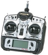
Graupner MX-16s |
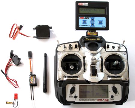
Graupner Mx-16s Jeti Set |
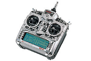
Graupner Mx-22s |
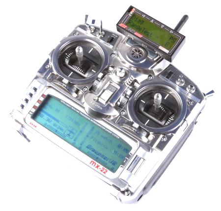
Graupner Mx-16s Jeti Set |
Spectrum DX7 |
Picture |
|
|
|
|
|
Channels |
35MHz, 8 Channels |
2,4GHz, 8 Channels, Transmission of telemetry data |
35MHz, 12 Channels |
2,4GHz, 12 Channels, Transmission of telemetry data |
2,4GHz, 7 Channels |
Shop Link |
|||||
Receivers |
Info about the Transmitter
The technical characteristics of the stations are listed in the shop. More detailed information can be found in the manufacturer's website.
Graupner MX-16s / MX-16s Set Jeti
The MX-16s and the MX-16s set Jeti differ only by the transmitter. The adjustment functions are the same.
The transmitter MX-16s is a 35MHz Transmitter. On this you can connect a 35MHz receiver with a crystal. The transmitter don't need a crystal. He got a Synthesizer-modul. So you can easy change the channels.
The transmitter MX-16s Set Jeti is a 2,4GHz transmitter. Inside the transmitter you have a Jeti-transmitter. On this you can connect each Jeti receiver (like the RMK2). The advantage of this system lies in the binding between the transmitter and receiver. On this it is not possible to disrupt the connection between the two from outside. In addition, the telemetry of the Kopter (height, battery charge, range, etc.) can be transfered and displayed on the Jeti box.
Quick Links:
![]() here you can read how to setup the MX16s/MX16s Set Jeti.
here you can read how to setup the MX16s/MX16s Set Jeti.
The settings should be chosen so that the channels match the settings of the FlightCtrl. Nevertheless, check!
Graupner MX-22 / MX-22 Set Jeti
The MX-22 and the MX-22 set Jeti differ only by the transmitter. The adjustment functions are the same.
The transmitter MX-22 is a 35MHz Transmitter. On this you can connect a 35MHz receiver with a crystal. The transmitter don't need a crystal. He got a Synthesizer-modul. So you can easy change the channels.
The transmitter MX-22 Set Jeti is a 2,4GHz transmitter. Inside the transmitter you have a Jeti-transmitter. On this you can connect each Jeti receiver (like the RMK2). The advantage of this system lies in the binding between the transmitter and receiver. On this it is not possible to disrupt the connection between the two from outside. In addition, the telemetry of the Kopter (height, battery charge, range, etc.) can be transfered and displayed on the Jeti box.
Setup of the MX-22
A brand new MX-22 needs a few settings
Changing stick mode to "mode 2" (gas left)
We recommend the stick mode 2 (see above). That is usually the easiest way to control a MikroKopter.
Therefore the mechanically stick neutralisation of the sticks must be changed (if not already done) Please refer the enclosed manual for that (Page 15)
Now the control mode must be changed in the setup of the transmitter.
ENT -> go into the setup
Reel -> go to "Base setup model" -> press the reel
- keep reel pressed ans scroll to "Stick mode"
- Press reel and scroll to "2"
ESC -> leave menu
Set modulation to PPM24
ENT -> go into the setup
Reel -> go to "Base setup model" -> press the reel
- keep reel pressed ans scroll to "Modulation"
- Press reel and scroll to "PPM24"
ESC -> leave menu
choose actualtors for the channels
ENT -> go into the setup
Reel -> go to "Control adjust" -> press the reel
- keep reel pressed ans scroll to the channel you want to change
- before the next step, please put the switch into the desired off-position; in exsample towards you
- Press reel and switch the switch into the on-position
- do the same with all actuators
ESC -> leave menu
Exsample channel setting:
Channel 5 -> two-stage switch 2 (SW2) -> i.e. Altitude control
Channel 6 -> three-stage switch 7 (Control 7) -> i.e. for GPS
Channel 7 -> Drehpoti links (Control 10) -> i.e. camera-angle
Channel 8 -> two-stage switch 1 (SW1) -> i.e. CareFree
Channel 9 -> three-stage 8 (Control 8)
Channel 10 -> two-stage switch 7 (SW7) -> i.e. LED Lights
Channel 11 -> two-stage switch left (Control 6) -> i.e. camera-angle
Channel 12 -> two-stage switch 8 right side (SW8) -> i.e. camera shutter
At the end you should check the setup in the channel-setup of the MikroKopter
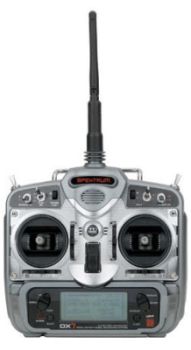
Spectrum DX7
The transmitter Spektrum DX7 is a 2,4GHz channel. At the transmitter, a receiver and a satellite-receiver can be operated.
The receiver who the servos can be connected, can not be used on the copter!
Only the little Satelliten-receiver can be used. How to connect it you find here: Spectrum
more transmitter
more infos for more transmitter you can find here: Weitere Sender

 Seite in
  Page en