|
Größe: 5921
Kommentar:
|
Größe: 5562
Kommentar:
|
| Gelöschter Text ist auf diese Art markiert. | Hinzugefügter Text ist auf diese Art markiert. |
| Zeile 54: | Zeile 54: |
| === Bedeutung der Parameter: === | === Meaning of the parameters: === |
| Zeile 56: | Zeile 56: |
| * ''max. current'': Legt die Obergrenze für den Motorstrom in Ampere fest. Bei höheren Strömen wird nicht abgeschaltet, sondern gedrosselt * ''Temperature Limiter'': Legt die maximale Board-Temperatur in °C fest. Bei höheren Temperaturen wird nicht abgeschaltet, sondern gedrosselt (ein Prozent pro 0,1°C) * ''PWM Scaling'': legt die maximale Leistung bei maximalem Setpoint fest. Dadurch kann man den maximalen Schub limitieren, ohne Auflösung bei der Ansteuerung (Sollwerte) einzubüßen. * ''Start PWM'': Eingestellte PWM beim Starten der Motoren. Wenn Motoren schlecht anlaufen, kann man diesen Wert modifizieren. * ''Current Scaling'': Dieser Wert dient dem individuellen Finetuning der Strommessung eines Reglers. * ''Reverse Direction'': Hier kann man die Drehrichtung eines Reglers über die Software umkehren. |
* Max. current: Sets the upper limit for the motor current in amperes. At higer currents it is not switched off but cut back * Temperature Limiter: Limits the maximum temperature of the board in °C. At higher temperatures are not turned off, but cut back (one percent per 0.1 ° C) * PWM Scaling: defines the maximum power at maximum setpoint. This allows you to limit the maximum thrust, without losing resolution on the gas control. * Start PWM: set PWM when you start the engines. When the motors start badly, you can modify this value. * Current Scaling: this value is used for individual fine tuning of the current measurement of a controller. * Reverse Direction: Here you can reverse the direction of a controller by software. |
| Zeile 63: | Zeile 63: |
| === Hinweise === * Man kann die Parameter eines einzelnen Reglers anhand seiner Adresse setzen oder auch alle gleichzeitig ("Any" wählen). * Es werden nur diejenigen Parameter gesetzt, welche auch aktiviert sind (vorderes Auswahlfeld). * Damit die Setting dauerhaft (also auch noch nach dem Einschalten) in den Reglern gespeichert werden, muss man die Option "Store in EEPROM" vor dem Schreiben aktivieren. * Es können die Voreinstellungen wieder geladen werden, wenn man den Button "Restore Default" drückt. Diese werden jedoch nur dauerhaft gespeichert, wenn man gleichzeitg die Option "Store in EEPROM" ausgewählt hat. * Es können nur Settings von Reglern gelesen und geschrieben werden, deren Gasmischanteil in der Mixertabelle größer als 0 ist, die also in der Lageregelung auch verwendet werden. |
=== Notes === * You can set the parameters of a single controller using its address, or even all at the same time (select "Any"). * Only activated (front chackbox) parameters are set. * To store the settings permanently (ie, even after restart) in the controllers you must activate the option "Store to EEPROM" before writing. * The default settings can be loaded again when the button "Restore Default" is pressed. However, these are stored permanently only if you have also selected the option "Store to EEPROM". * Only settings of controllers whose gas mixing in the mixer table is greater than 0, which means are then used in the attitude control, can be written and read. |
| Zeile 74: | Zeile 73: |
| Siehe auch: [[Firmware-0.80|Firmware 0.80]] | See also: [[en/Firmware-0.80|Firmware 0.80]] |
| Zeile 76: | Zeile 75: |
| == Adressauswahl == Jeder Motor benötigt eine eindeutige Adresse. Deshalb werden den BL-Reglern Adressen von 1-8 vergeben. |
== Address selection == Each engine requires a unique address. Therefore the BL controls addresses are assigned by 1-8. |
| Zeile 79: | Zeile 78: |
| Bei der BL-Ctrl V2.0 wird die Motoradresse per Lötjumper (aus Lötzinn) auf der Platine eingestellt. | On BL-Ctrl V2.0 the motor address is set on the board using jumpers (use solder). |
| Zeile 83: | Zeile 82: |
| Dabei gilt: ||'''Adresse (Motor)''' ||'''1-2''' ||'''2-3''' ||'''4-5''' || ||1 ||offen ||offen ||offen || ||2 ||offen ||geschlossen ||offen || ||3 ||geschlossen ||offen ||offen || ||4 ||geschlossen ||geschlossen ||offen || ||5 ||offen ||offen ||geschlossen || ||6 ||offen ||geschlossen ||geschlossen || ||7 ||geschlossen ||offen ||geschlossen || ||8 ||geschlossen ||geschlossen ||geschlossen || |
Where: ||'''Adress (Motor)''' ||'''1-2''' ||'''2-3''' ||'''4-5''' || ||1 ||open ||open ||open || ||2 ||open ||closed ||open || ||3 ||closed ||open ||open || ||4 ||closed ||closed ||open || ||5 ||open ||open ||closed || ||6 ||open ||closed ||closed || ||7 ||closed ||open ||closed || ||8 ||closed ||closed ||closed || |
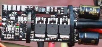
Brushless-Controller Version 2.0

Shoplink currently under translation
main Features
- ATMEGA168 with 16kB Flash
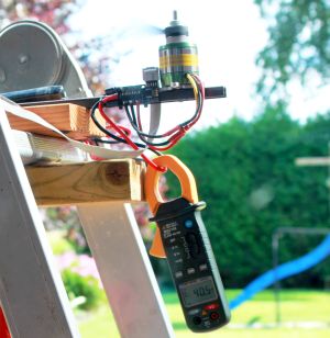
Current: 35A continuos & 40A Peak (provided there is good cooling)
Voltage: up to 5s-Lipo (18,5V)
- Sizes: 21 x 44mm (like the V1.0)
Capacitors: a second capacitor is required for currents > 20A
Features
- Current measurement
Temperature measurement
Voltage measurement
11Bit Resolution (2047 steps)
I2C-Bus for MikroKopter
- serial port for MKTool
- PPM-input (Important: if the PPM-input is used make sure the 4-5 jumper is not closed)
Jumper to address the Addresses 1-8
Configurable by the I2C-bus using Koptertool -> the Koptertool can remain connected to the Navi or the FC
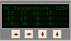
Show temperatures in the virtual display

Display of the measured values in MKTool
(in this case the BLC must directly connected to the MKUSB)
Display of the temperatures in the display Jeti
See also: JetiBox
Safety
- adjustable current limit, gently slows down and doesn't shut off
- gentle reduction of temperature
doesn't start at> 85 ° C (if the engine is blocked for some time)
Adjustable
The settings are recordered at the start of the MK into the BL-Controller.
The settings can be stored manually in the single controllers.
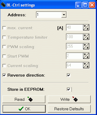
In order to show the BL-Ctrl menu press Ctrl + Settings.
Meaning of the parameters:
- Max. current: Sets the upper limit for the motor current in amperes. At higer currents it is not switched off but cut back
- Temperature Limiter: Limits the maximum temperature of the board in °C. At higher temperatures are not turned off, but cut back (one percent per 0.1 ° C)
- PWM Scaling: defines the maximum power at maximum setpoint. This allows you to limit the maximum thrust, without losing resolution on the gas control.
- Start PWM: set PWM when you start the engines. When the motors start badly, you can modify this value.
- Current Scaling: this value is used for individual fine tuning of the current measurement of a controller.
- Reverse Direction: Here you can reverse the direction of a controller by software.
Notes
- You can set the parameters of a single controller using its address, or even all at the same time (select "Any").
- Only activated (front chackbox) parameters are set.
- To store the settings permanently (ie, even after restart) in the controllers you must activate the option "Store to EEPROM" before writing.
- The default settings can be loaded again when the button "Restore Default" is pressed. However, these are stored permanently only if you have also selected the option "Store to EEPROM".
- Only settings of controllers whose gas mixing in the mixer table is greater than 0, which means are then used in the attitude control, can be written and read.
See also: Firmware 0.80
Address selection
Each engine requires a unique address. Therefore the BL controls addresses are assigned by 1-8.
On BL-Ctrl V2.0 the motor address is set on the board using jumpers (use solder).
Where:
Adress (Motor) |
1-2 |
2-3 |
4-5 |
1 |
open |
open |
open |
2 |
open |
closed |
open |
3 |
closed |
open |
open |
4 |
closed |
closed |
open |
5 |
open |
open |
closed |
6 |
open |
closed |
closed |
7 |
closed |
open |
closed |
8 |
closed |
closed |
closed |
Elkos
Dem BL-Regler liegen zwei Elkos bei. Den zweiten Elko benötigt man ab 20A. Es schadet auch nicht, wenn man immer beide Elkos bestückt.
Wichtig: Polung beachten - die weisse, dicke Minus-Markierung der Elkos muss zu den Platinenrändern
Schaltplan
http://mikrocontroller.com/files/BL_Ctrl_V2_0_Doku.pdf
BL-Ctrl im Okto-Verteiler
Sonstiges
- die Softwarequellen diese BL-Reglers sind nicht offen
falls es ein Software-Update gibt: die Software darf nur seriell per KopterTool eingespielt werden. Per SPI würde man sich den Bootloader löschen - der ist nicht öffentlich


