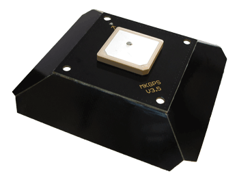
MK-GPS V3.5 |

Shoplink: MK GPS V3.5
Inhaltsverzeichnis
MK-GPS V3.5
The new MK-GPS V3.5 is a GPS receiver with integrated compass. New are also a Master and a Salve connection. So you can use the MK-GPS V3.5 as a single modul, or as a twin system on your redundant copter.
Beside the usual American GPS satellites, the Russian Glonas satellite systems or the Chinese BeiDou satellite systems can be received. For suppressing external interference sources (e.g. video systems), the GPS receiver has been equipped with an RF preamplifier, and a SAW RF Filter.
The MK-GPS is required for functions like
PositionHold (or PH)
ComingHome (or CH)
Waypoint flight (Waypoints)
- Save the route to SD card in a LOG File
View the current position on the 'OSD' map in the KopterTool
Display distance and speed in the Graupner HoTT-Telemetrie
Aligning a camera at a certain point: PointOfInterest
All functions that you can use with the navigation system on your MikroKopter, are described here: Features
INFO:
YOu can use the MK-GPS V3.5 only with a MikroKopter Software from version V2.14!
Technical data
- Weight: 29g (MK-GPS V3.5 include GPS Shield)
- Dimensions: 90 x 90mm (Hole distanced: 44,6mm x 44,6mm)
Voltage: 5V (is supplied by FlightCtrl/NaviCtrl)
- The latest UBlox technology
- Twin compass system
- LEDs for status display
- Redundant configuration
- Integrated RF preamplifier
- Integrated Integrated SAW RF Filter
- GPS
- Glonas
BeiDou
- Japanese QZSS system
- incl. GPS Shield for improved reception
GPS / Glonas / BeiDou
Beside the usual American GPS satellites, the Russian Glonas satellite systems or the Chinese BeiDou satellite systems can be received.
So you have much more satellites for a much better navigation (especially in areas with inadequate GPS coverage).
You can set which satellite you want to use.
Auf der microSD Karte (in der NaviCtrl / FlightCtrl V3.0) befindet sich die Datei SETTINGS.ini.
Mit einem Text-Editor kann man diese Datei öffnen und den Wert für GPS_SYSTEM_CFG ändern:
- 1 = GPS + Glonas (Default)
2 = GPS + BeiDou
- 3 = GPS
- 4 = Glonas
5 = BeiDou
Zusätzlich kann das Japanese QZSS system per GPS_QZSS_DGPS_ON (de)aktiviert werden:
- 0 = OFF (Default)
- 1 = ON
GPS Info
Via the KopterTool you can see:
- the current GPS deviation (the copter should be at the bottom)
 the center position can be moved by right-clicking with the mouse
the current signal strength of the satellite
(Note: outside at least one satellite should have 50dB signal strength.
A GPS-Shield is recommended for a better reception.)- Position of the satellites in the sky:
- light-green satellites: Satellite is used with SBAS-correction data for the navigation
- dark-green satellites: Satellite is used without SBAS-correction data for the navigation
- turquoise satellites: Satellite is not used yet for navigation
- red satellites: signal is bad or Satellite is not useable
- lila satellites: transmits SBAS-correction data
GPS Navigation-Satellites have the letter "G", SBAS-Satellites "S".
The number is the ID of the satellite (PRN Code).
Details about the satellite is also be shown by moving the mouse over the satellite.
![]() Note: If that is in use, the KopterTool directly accesses the GPS module and the NaviCtrl reports "Error: No GPS Communication"
Note: If that is in use, the KopterTool directly accesses the GPS module and the NaviCtrl reports "Error: No GPS Communication"
Calibrate Compass
The compass (and the GPS) is needed for the automated control of the MikroKopter.
Therefore a new compass must be calibrated once for a proper function.
If the compass has not been calibrated, compass and GPS supported features can not be used and you can not start the copter.
An error message (error 31) is then displayed via the telemetry.
A recalibration of the compass is usually only necessary when the Kopter fly under the "PositionHold" function in circles at a remote location.
The calibration
Please note
Calibrate the copter outside, far away from magnetic influences!
During the calibration you have to turn the copter completely around the axis.
The following applies: If you calibrate the compass precisely, the copter will fly perfectly.
If the copter is flying in circles (with activated function PositionHold and in an altitude above houses and trees), you better calibrate the compass new.
When you have problems after the calibration (e.g. an err22), a magnetic problem on your copter can be the problem.
Informations for the "magnetic error" can be found here:: MagnetError
The calibration will be done in 5 steps:
Step |
Funktion |
Beispielansicht / Funktion |
Switch ON the Transmitter and connect the Copter with the Lipo. |
|
|
Step 1 |
Nick down |
|
Step 2 |
Pull Nick down 1x |
|
Calibration of the X-Axis (Nick-Axis) |
The Kopter with the front |
|
Rotate the Kopter |
Rotate the Kopter by 90°. |
|
Calibration of the Y-Axis (Roll-Axis) |
Rotate the Kopter a couple times completely over the Roll-Axis until the buzzer stops with the clicking. |
|
Step 3 |
Pull Nick 1x down |
|
Step 4 |
Pull Nick 1x down |
|
Calibration of the Z-Axis |
INFO: Here it doesn't matter if the Kopter shows with the X or Y-Axis towards South (North). |
|
Step 5 |
Pull Nick 1x down |
|
Now that the Kopter "beeped" 2x after a successful calibration that part is done.
Videos
Check the calibration
You can now check the calibration of the compass in the KopterTool or also with a suitable transmitter.
Please do this also outside, far away from magnetic influences!
Here you have to check two values:
- MAG (or Field) = This should be around 100%
- Inclination (Incl) = This should be nearly the same value as the one in brackets
IMPORTANT:
To see the right values you have to calibrate the Gyros first (throttle up + yaw left).
Without calibration you will still see 100% and no Inclination.
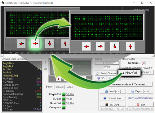
Check via KopterTool
Here you use:
a MK_USB or a wireless connection between Copter and Computer
+- you have calibrate the Gyros (throttle up + yaw left).

In the main window of the KopterTool click the button [NaviCtrl].
Under the virtual display klick the red arrow (left or right) until the window "Magnetic Field" displayed.
The value for "Field" must be around 100% and the value for Inclination around the value you see in brackets.
(If the value for "Field" (or for "Inclination") is ~10%-15% higher/lower then 100%, recalibrate the compass)
Check via HoTT transmitter
To see the right values of the calibration you have to calibrate the Gyros again (throttle up + yaw left).
Now you can check the magnetic value in the lower display of the Graupner HoTT transmitter.
How to open it:
With the right "four-way button" select the middle button SET to open the Menu
Go down to Telemetry and press SET
In the telemetry window choose setting & data view and press SET
In the next menu press the right button until you see the "Text-telemetry"
To change the view of "0m/s" to "MAG" press SET again.
The value for "MAG" must be around 100% and the value for Inclination (incl) around the value you see in brackets.
If the value for "Field" (or for "Inclination") is ~10%-15% higher/lower then 100%, recalibrate the compass!
NMEA
From software version 2.02a (FlightCtrl/NaviCtrl) we can also send the NMEA signal from the UBlox GPS.
If you use a camera with integrated data logging you can use this data to save the position data n the pictures.
You can get the NMEA signal on the contacts PIN9 (TxD) + PIN7 (GND) of your serial output (FlightCtrl V3) or Debug port (NaviCtrl). The data records RMC & GGA are sent with 57600 Baud '(default) / TTL (5V).
Setting
To send the NMEA signal via PIN9 you need a microSD card (max. 2GB/FAT16) in your FlightCtrl V3 / NaviCtrl.
On this microSD card you find the file "SETTINGS.INI". You can open and change this file via an editor.
The output interval of the NMEA signal is set with the parameter NMEA_INTERVAL.
# NMEA Output interval in ms (0 = disabled)
NMEA_INTERVAL = 0
By default, the output is disabled (NMEA_INTERVAL = 0)
If you need a signal e.g. every 500ms set here a "500" (NMEA_INTERVAL = 500)
The output is 57600 baud. From SW-Version 2.20 you can change the output speed
under "# Baudrate for the PC-UART".
IMPORTANT:
If you change the baud in your SETTINGS.INI all data will be send in this speed !!!
So if you use e.g. a wireless connection between Copter <-> PC you also have to change here the speed!
INFO:
If there is no Parameter "# NMEA Output interval in ms" in your SETTINGS.INI, delete the "SETTINGS.ini" on your microSD card. After you power up the copter the Software on your copter will create a new "SETTINGS.INI" with the needed parameters.
Check output
If you set a NMEA_INTERVAL in your SETTINGS.INI, you can check the output data in the terminal window of your KopterTool.
For this "click" the button [-> NaviCtrl] in your KopterTool and then the
button [Firmware update & Terminal] to open the terminal window.
Here you should now see some data like this:
Connection
In these examples the connection is described:
More informations about NMEA
More informations about NMEA format you can find here:


