Electronic Connections |
Inhaltsverzeichnis
- Electronic Connections
- Connection of receiver, speed controlers (ESC) and batteries (LiPo)
- Connecting powerlines to the flight controler
- Connecting the brushless controlers (ESC)
- Connecting the motors
- Connecting other peripherals
- Example of a fully wired up flight controler and brushless controler
- Tips
Electronic Connections
Overview
Here are the motor (and ESC) numbers, positions, and directions of rotation as seen from behind and above the MK:
Motor |
Position |
Turns |
#1 |
front |
right (clockwise) |
#2 |
rear |
right (clockwise) |
#3 |
right |
left (counterclockwise) |
#4 |
left |
left (counterclockwise) |
Tip: ESC/motor #3 is located at 3 o'clock
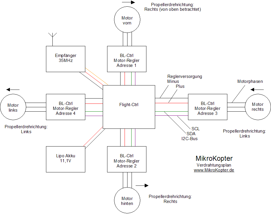
(Klick for higher resolution image)
Connection of receiver, speed controlers (ESC) and batteries (LiPo)
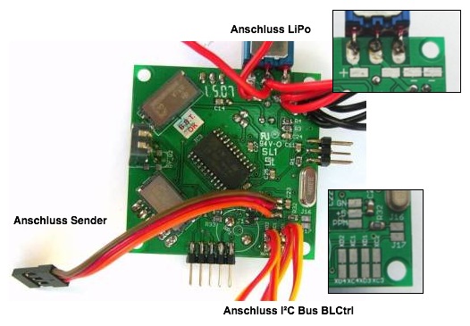
The receiver is connected with a three lead servo wire: +5V, GND and PPM (red, brown/black, orange/yellow).
The LiPo is connected over 2 wires (+ = red, - = brown/black). For lower power applications the BLCtrl power connections are also connected over 2 wires. For higher powered MKs it is safer to create a wiring harnes to connect the ESCs directly to the batteries, and connect the FC through an additional branch to the same harnas. Note that higher power applications may need more powerfull ESCs. For the Holger ESCs the normal wire thickness noted below should suffice).
The I²C-Bus as control bus for the brushless controlers is connected over two or three wires. In the image a two wire connection is shown (SDA = red, SCL = orange). Alternatively you can use 3 wire servo leads and add a GND connection.
cable-Type |
min. cable Size |
LiPo -> Power-Distribution |
1mm² (1.5 or 2 mm² for higher powered applications) |
Power-Distribution -> FlightCtrl |
0,75mm² (can be 0.3-4 mm² if the batteries are directly banched off of the batteries for higher powered applications) |
Power-Distribution -> BL-Ctrl |
0,75mm² (1 or 1.5 mm² for higher powered applications) |
BL-Ctrl -> Engines |
0,5mm² (0.75 to 1 mm² for high power systems) |
The I²C connection pads are very close to a mounting hole in the flight controler. Either use plastic or nylon bolts to avoid short-circuits, or connect only 2 wires and branch the different ESCs off at a later point.
![]() Note: Each of the pairs of pads provides the same signal pair (XD# = SDA, XC# = SCL) These are all connections to the same I²C Bus
Note: Each of the pairs of pads provides the same signal pair (XD# = SDA, XC# = SCL) These are all connections to the same I²C Bus
Using power distribution boards
Distribution boards make the wiring much simpler
See also:
Connecting powerlines to the flight controler
The FlightCtrl has two sets of pads for +12V und GND (Minus). In this image red = Plus and black = Minus. In this lower power application the Lipo is directly connected and the ESCs are powered off of the FC. It is also possible, and advised for higher power applications, to power the ESCs directly off of the LiPos before the FC and switch by creating a wiring harnas or power distribution PCB. In that case some thinner wire can be used to connect the FC to the power harnas.
Make sure you connect the LiPo power before the FC on/off switch. If the ESCs are fed off of the 11-12V FC power-supply, they are connected after the switch. This does result in a different behaviour:
- ESCs fed off of the FC: If the battery is connected but the switch is off, nothing gets powered. If the switch is turned on both the FC and ESCs are powered up.
ESCs fed off of the LiPo directly, and FC through a sidebranch: If the battery is connected, the ESCs immediately power up. The FC only powers up after the switch is set to on. Note that normally the ESCs should only beep (actually they cause a hum in the motor windings which is heard as a beep), not turn the propellors. However, in higher power applications make sure you keep away from the propellers when the ESCs are powered up. Safety first.
using the mini power distribution
With this small PCB it is very easy to realize the distribution. The Cables don't have to soldered directly to the FlightControl
Note in this case: If the FC is connected via the molex-cable, the switch on the FC can't be used. The FC is powered up when the supply is connected to the MiniPowerDistribution
See also: MiniPowerDistribution
Connecting the brushless controlers (ESC)
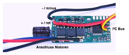
The three wires in the bottom of the image (blue, red, black) go to the brushless motor. The thicker black (GND) and red (11-12V) wires at the top are the power lines to the ESC. They are connected to the battery either through the FC or directly through a wire harnas or power distribution PCB. The red and yellow wire at the right are the I²C connections (red = SDA, yellow = SCL in this image, note that you can also use 3 wire servo leads and connect GND as third wire).
BL-Ctrl |
|
J6 |
XC1, XC2, XC3, XC4 |
J7 |
XD1, XD2, XD3, XD4 |
The sequence of connecting the brushless controlers to the 4 I²C Pads is irrelevant as this is a simple two wire bus. In fact you can also connect all ESCs to a single pair of pads using a wiring harnas or PCB of your own design.
![]() WARNING: Protect the ESCs from humidity to avoid destroying the Mosfets. Make sure to use heatshrink or Plasticspray to protect the ESCs. However don't fully enclose the ESCs as the Mosfets can get warm, may need to be cooled.
WARNING: Protect the ESCs from humidity to avoid destroying the Mosfets. Make sure to use heatshrink or Plasticspray to protect the ESCs. However don't fully enclose the ESCs as the Mosfets can get warm, may need to be cooled.
Connecting the motors
Motor 1 (front) and 2 (rear) turn right (clockwise), 3 (right) and 4 (left) turn left (counterclockwise).
The direction of turning is determined by the three wire connection to the ESC. IF a motor turns in the wrong direction just switch two wires.
Connecting other peripherals
Receiver, Servos and others can be connected to the FlightControl. Please see this for the details: FlightCtrl_ME_2_1
Note that on some systems, the channel numbering is different. The MKTool allows you to assign the correct control function to the correct control. The camera tilt control from your transmitter/receiver should be assigned to J7 / camera tilt.
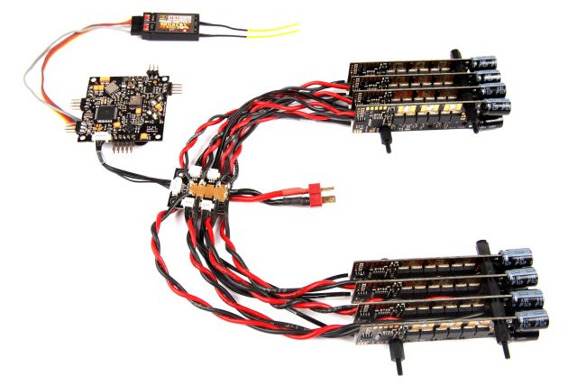
Example of a fully wired up flight controler and brushless controler
Old PCBs:
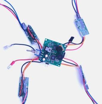
New Electronic with Mini8 Distribution
Tips
Soldering a Power Distribution ( german Text but u can see what its all about in the Pictures):
 ToDo: Would probably be a good idea to show some different wire harnasses, and also include some examples of connectors and their pros and cons.

