Bluetooth-Modul |
Inhaltsverzeichnis
Shoplink
SET: Bluetooth-Module F2M03GXA + BT-Adapter + Parts: Shoplink
Bluetooth Adapter V1.0 (BT-AP)
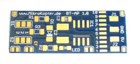
The board works as a power supply and level adjustment for the Bluetooth Module F2M03GXA.
This means that the BT module can be operated on a microcontroller with a 5V supply.
For an easier configuration the direction of RxD & TxD can be changed with solder jumper.
Instructions regarding the start up
![]() To avoid (self-inflicted) damages at the BT-Module necessarily proceed as follows:
To avoid (self-inflicted) damages at the BT-Module necessarily proceed as follows:
- First at all assemble the BT-Adapter PCB.
- Solder only the connection to the Bluetooth-Module if you have verified the correct function of the circuit.
Connect the BT-Adapter over a ribbon cable to the FlightCtrl.
It's enough if only the contacts #2 (+5V) and #7 (GND) been soldered.
For that reason you can use also the bigger pads.
The LED must flash and between the pins BT36 & BT37 you should measure 3,3V.
(See Schematic and assembly)
If that is OK you can solder the adapter to the module.
Assembly Bluetooth-Adapter and Bluetooth-Module
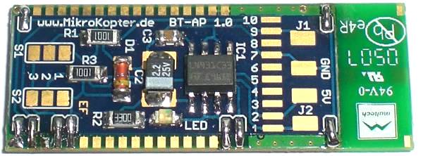
The very thin PCB-board (only 0,3mm) will be simply soldered to the bottom of the Bluetooth-Module.
![]() ATTENTION: Tantal capacitors have the mark at the anode (+). "marking=anode" is also described in the PDF-File of the Elkos.
ATTENTION: Tantal capacitors have the mark at the anode (+). "marking=anode" is also described in the PDF-File of the Elkos.
Tipp:
To connect the adapter board with the module you can use also single strands of a cable.
To the pins 1-10 (necessary are only the pins 1;2;7;9) you can solder very simple the ribbon cable:

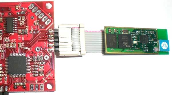
The ribbon cable should be connected as shown.
If you connect it to the other side you disturb the Bluetooth antenna and also the receiving.
Connection to the Flight-Ctrl
You need to set the solder jumper as follows:
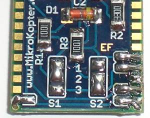
Jumper
- S1: 1-2
- S2: 2-3
The complete Bluetooth-Module will be connected to the 10pin connector at the FlightCtrl.
![]() If you use the GPS-System the module will be connected to the "Debug"-Port of the NaviCtrl .
If you use the GPS-System the module will be connected to the "Debug"-Port of the NaviCtrl .
Connecting to the PC
You need to set the solder jumper as follows:
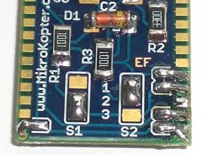
Jumper
- S1: 2-3
- S2: 1-2
Connecting to the MKUSB
The complete Bluetooth-Module will be connected to the MK-USB.
The jumper on the MK-USB need to be closed to supply the Bluetooth-Module with power.
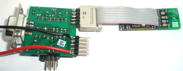
Connecting to the SerCon
Who still uses a Sercon can do this also.
Here you need to supply power to the PCB over the displayed spots +5V (red cable) and GND (black cable).
Schematic
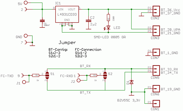
BT-AP10/Bluetooth-Adapter-PCB_V10_sch.pdf
Layout of placement
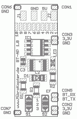
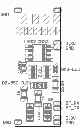
BT-AP10/Bluetooth-Adapter-Platine_V10_brd.pdf
Configuration
![]() NOTE The Bluetooth-Modules out of our shop are already programmed and tested.
NOTE The Bluetooth-Modules out of our shop are already programmed and tested.
The settings are:
Device Name: MikroKopter_BT
Password: 0000
Baud: 57600
Slave (for the connection to the MikroKopter)
After a successful assembly the Bluetooth-Module can be detected with those datas over a PC/Laptop or a cellphone with Bluetooth.
If you want to use two Bluetooth modules to get a greater range a second Bluetooth module need to be connected to the MK-USB.
(The manufacturer declares for the Bluetooth module F2M03GXA a range of ~350 mtr.)
Two settings for the Bluetooth Module need to be changed on the PC-side:
- The solder jumper need to be changed.
The module need to be set to Master .
With those settings you can pair both Bluetooth Modules with a secure connection.
Pairing two Bluetooth Modules
Two BT-Modules can be easily combined with each other via the configuration tool (pairen).
This can be done with the program "Free2move Configuration Software" Download
Step by Step Instruction:
Connect Bluetooth-Modul to FlightControl (solder jumper on BT Adapter: S1:1-2 / S2:2-3)
Connect Bluetooth-Modul to MK-USB (place jumper on MK-USB, solder jumper on BT Adapter: S1:2-3 / S2:1-2)
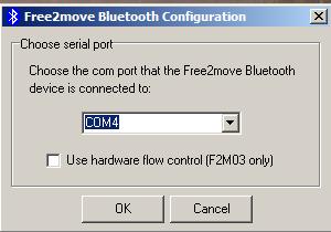
Open program "Free2move Configuration Software" .
Choose COM Port from MK-USB and click "OK" .
Example View:
- Once the module has been detected the program opens.
Example View:
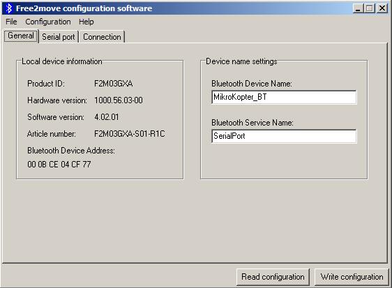
Now you click on the tab "Connection".
Change "Device Mode:" now to "Connecting (master)" and than click on "Find device..." .
Example View:
- Place a checkmark at "Enable Remote Name Request" and click on "Search" on the right.
- In the window below all accessible Bluetooth connections are listed.
- Click on the Bluetooth-Module of the Kopter and click "OK" .
Example View:
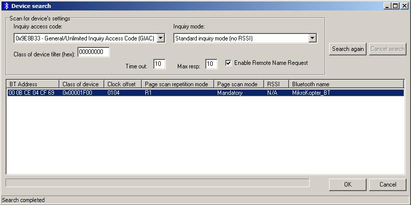
- Now the "Bluetooth address" will be displayed right below.
- Finish all by clicking on "Write Configuration" .
Example View:
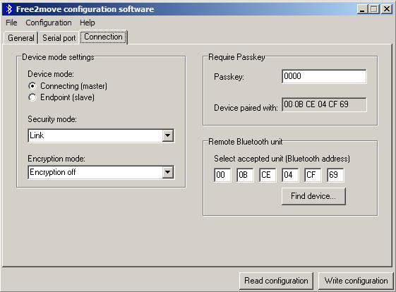
- READY
If you open now the KopterTool a connection between both Bluetooth-Modules should be established and the transferred datas been displayed.
Link
see also: Do-it-yourself solution: BTAP
- KategorieMK-Baugruppe/de

 Seite in
  Page en