|
Größe: 7383
Kommentar:
|
← Revision 26 vom 18.12.2014 13:45 ⇥
Größe: 7101
Kommentar:
|
| Gelöschter Text ist auf diese Art markiert. | Hinzugefügter Text ist auf diese Art markiert. |
| Zeile 3: | Zeile 3: |
| ||<tablewidth="520px" tablestyle="text-align: center;"bgcolor="#FAD165"> {{http://mikrocontroller.cco-ev.de/images/deu.gif}} Seite in [[BT-AP10|deutsch]] ||<bgcolor="#FAD165"> {{http://mikrokopter.de/images/fra.gif}} Page en [[fr/BT-AP10|français]] || | ||<tablewidth="520px" tablestyle="text-align: center;"bgcolor="#ffffa0"> {{http://mc.mikrocontroller.com/images/deu.gif}} Seite in [[BT-AP10|deutsch]] ||<bgcolor="#ffffa0"> {{http://mikrokopter.de/images/fra.gif}} Page en [[fr/BT-AP10|français]] || |
| Zeile 11: | Zeile 11: |
| SET: Bluetooth-Modul F2M03GXA + BT-Adapter + Bauteile: [[https://www.mikrocontroller.com/index.php?main_page=product_info&cPath=86&products_id=210|Shoplink]] | SET: Bluetooth-Module F2M03GXA + BT-Adapter + Parts: [[https://www.mikrocontroller.com/index.php?main_page=product_info&cPath=86&products_id=210|Shoplink]] |
| Zeile 14: | Zeile 14: |
| {{attachment:BT-AP10_.jpg}} | {{attachment:BT-AP10/BT-AP10_.jpg}} |
| Zeile 16: | Zeile 16: |
| Die Platine dient zur Spannungsversorgung und als Pegelanpassung für das Bluetooth Modul [[F2M03GXA|F2M03GXA.]]<<BR>> Damit kann das BT-Modul an einem Mikrocontroller mit 5V-Versorgung betrieben werden.<<BR>> Zur einfacheren Konfiguration kann die Richtung von RxD & TxD mit Lötjumpern verändert werden. |
The board works as a power supply and level adjustment for the Bluetooth Module [[F2M03GXA|F2M03GXA.]]<<BR>> This means that the BT module can be operated on a microcontroller with a 5V supply.<<BR>> For an easier configuration the direction of RxD & TxD can be changed with solder jumper. |
| Zeile 20: | Zeile 20: |
| = Hinweise bei der Inbetriebnahme = /!\ Um (selbst verschuldete) Schäden am BT-Modul zu vermeiden, unbedingt folgendermaßen vorgehen: <<BR>><<BR>> |
= Instructions regarding the start up = /!\ To avoid (self-inflicted) damages at the BT-Module necessarily proceed as follows: <<BR>><<BR>> |
| Zeile 23: | Zeile 23: |
| - Zuerst die BT-Adapterplatine bestücken.<<BR>> - Den Anschluss an das Bluetooth-Modul erst löten, wenn man zuvor die korrekte Funktion der Schaltung überprüft hat.<<BR>><<BR>> |
- First at all assemble the BT-Adapter PCB.<<BR>> - Solder only the connection to the Bluetooth-Module if you have verified the correct function of the circuit.<<BR>><<BR>> |
| Zeile 26: | Zeile 26: |
| Dazu schließt man den BT-Adapter per Flachbandkabel an die FlightCtrl an. <<BR>> Es reicht, wenn dazu nur die Kontakte 2 (5V) und 7 (GND) angelötet werden. <<BR>> Dazu kann man auch die großen Pads nutzen.<<BR>> Dann muss die LED leuchten und zwischen den Pins BT36 & BT37 muss man 3,3V messen können.<<BR>> ([[#Schaltplan|Siehe Schaltplan und Bestückung]])<<BR>><<BR>> |
Connect the BT-Adapter over a ribbon cable to the !FlightCtrl. <<BR>> It's enough if only the contacts #2 (+5V) and #7 (GND) been soldered. <<BR>> For that reason you can use also the bigger pads.<<BR>> The LED must flash and between the pins BT36 & BT37 you should measure 3,3V.<<BR>> ([[#Schematic|See Schematic and assembly]])<<BR>><<BR>> |
| Zeile 32: | Zeile 32: |
| Ist das OK kann der Adapter an das Modul gelötet werden. | If that is OK you can solder the adapter to the module. |
| Zeile 35: | Zeile 35: |
| = Montage/Bestückung Bluetooth-Adapter und Bluetooth-Modul = Die sehr dünne Platine (nur 0,3mm) wird einfach von der Unterseite an das Bluetooth-Modul gelötet. <<BR>><<BR>> |
= Assembly Bluetooth-Adapter and Bluetooth-Module = The very thin PCB-board (only 0,3mm) will be simply soldered to the bottom of the Bluetooth-Module. <<BR>><<BR>> |
| Zeile 38: | Zeile 38: |
| /!\ ACHTUNG: Tantal Kondensatoren haben den Strich bei der Anode (+). "marking=anode" steht auch im PDF des Elkos.<<BR>> {{attachment:BT_Photo1.jpg}}<<BR>><<BR>> |
/!\ ATTENTION: Tantal capacitors have the mark at the anode (+). "marking=anode" is also described in the PDF-File of the Elkos.<<BR>> {{attachment:BT-AP10/BT_Photo1.jpg}}<<BR>><<BR>> |
| Zeile 42: | Zeile 42: |
| Zum Verbinden der Adapterplatine mit dem Modul können auch die einzelnen Litze eines Kabels genutzt werden.<<BR>><<BR>><<BR>> | To connect the adapter board with the module you can use also single strands of a cable.<<BR>><<BR>><<BR>> |
| Zeile 44: | Zeile 44: |
| An den Pins 1-10 (notwendig sind nur Pins 1;2;7;9) kann man sehr einfach das Flachbandkabel anlöten: <<BR>> {{attachment:BT_Photo2Ka.jpg}}<<BR>><<BR>> |
To the pins 1-10 (necessary are only the pins 1;2;7;9) you can solder very simple the ribbon cable: <<BR>> {{attachment:BT-AP10/BT_Photo2Ka.jpg}}<<BR>><<BR>> |
| Zeile 47: | Zeile 47: |
| Das Flachbandkabel sollte so wie gezeigt verlegt werden. <<BR>> Eine Verlegung zur anderen Seite behindert die Bluetooth Antenne und somit dem Empfang. |
The ribbon cable should be connected as shown. <<BR>> If you connect it to the other side you disturb the Bluetooth antenna and also the receiving. |
| Zeile 53: | Zeile 53: |
| = Anschluss an die Flight-Ctrl = Die Lötjumper müssen dann wie folgt gesetzt sein: <<BR>> {{attachment:BT_JP_FC.jpg}} |
= Connection to the Flight-Ctrl = You need to set the solder jumper as follows: <<BR>><<BR>> {{attachment:BT-AP10/BT_JP_FC.jpg}} <<BR>> |
| Zeile 62: | Zeile 62: |
| Angeschlossen wird das komplette Bluetooth-Modul an den 10pin Anschluss der !FlightCtrl.<<BR>><<BR>> | The complete Bluetooth-Module will be connected to the 10pin connector at the !FlightCtrl.<<BR>><<BR>> |
| Zeile 64: | Zeile 64: |
| {{attachment:BT_FC.jpg}} | {{attachment:BT-AP10/BT_FC.jpg}} |
| Zeile 68: | Zeile 68: |
| {i} Bei Verwendung des GPS-Systems, wird das Modul an den "Debug"-Port der !NaviCtrl angeschlossen.<<BR>><<BR>> | {i} If you use the GPS-System the module will be connected to the "Debug"-Port of the !NaviCtrl .<<BR>><<BR>> |
| Zeile 72: | Zeile 72: |
| = Anschluss am PC = Die Lötjumper müssen dann wie folgt gesetzt sein: <<BR>> {{attachment:BT_JP_CFG.jpg}} |
= Connecting to the PC = You need to set the solder jumper as follows: <<BR>> {{attachment:BT-AP10/BT_JP_CFG.jpg}} |
| Zeile 81: | Zeile 81: |
| == Anschluss an MKUSB == Das komplette Bluetooth-Modul wird an das MK-USB angeschlossen. <<BR>> Der Jumper auf dem MK-USB muss hierbei geschlossen sein, um das Bluetooth-Modul zu versorgen.<<BR>><<BR>> |
== Connecting to the MKUSB == The complete Bluetooth-Module will be connected to the MK-USB. <<BR>> The jumper on the MK-USB need to be closed to supply the Bluetooth-Module with power.<<BR>><<BR>> |
| Zeile 88: | Zeile 88: |
| == Anschluss an den SerCon == Wer noch ein Sercon nutzt, kann auch hieran das Bluetooth-Modul anschließen.<<BR>> Dabei muss die Platine z.B. über die hier abgebildeten Stellen mit +5V (rotes Kabel) und GND (schwarzes Kabel) versorgt.<<BR>><<BR>> |
== Connecting to the SerCon == Who still uses a Sercon can do this also.<<BR>> Here you need to supply power to the PCB over the displayed spots +5V (red cable) and GND (black cable).<<BR>><<BR>> |
| Zeile 92: | Zeile 92: |
| {{attachment:BT_PhotoSercon.jpg}} Dabei wird die Platine z.B. an den hier abgebildeten Stellen mit +5V (rotes Kabel) und GND (schwarzes Kabel) versorgt. |
{{attachment:BT-AP10/BT_PhotoSercon.jpg}} |
| Zeile 98: | Zeile 96: |
| = Schaltplan = {{attachment:BT-SCH_kl.gif}} |
= Schematic = {{attachment:BT-AP10/BT-SCH_kl.gif}} |
| Zeile 101: | Zeile 99: |
| [[attachment:Bluetooth-Adapter-Platine_V10_sch.pdf]] | [[attachment:BT-AP10/Bluetooth-Adapter-PCB_V10_sch.pdf]] |
| Zeile 103: | Zeile 101: |
| = Bestückungsplan = {{attachment:BT-BST.gif}} {{attachment:BT-BST2.gif}} |
= Layout of placement = {{attachment:BT-AP10/BT-BST.gif}} {{attachment:BT-AP10/BT-BST2.gif}} |
| Zeile 106: | Zeile 104: |
| [[attachment:Bluetooth-Adapter-Platine_V10_brd.pdf]] | [[attachment:BT-AP10/Bluetooth-Adapter-Platine_V10_brd.pdf]] |
| Zeile 109: | Zeile 107: |
| = Konfiguration = Die Bluetooth-Module aus dem Shop sind bereits programmiert und getestet.<<BR>><<BR>> |
= Configuration = (!) '''__NOTE__''' The Bluetooth-Modules out of our shop are already programmed and tested.<<BR>><<BR>> |
| Zeile 112: | Zeile 110: |
| Die Einstellungen sind: <<BR>> * Device Name: MikroKopter_BT * Passwort: 0000 * 57600 baud * Slave (für den Anschluss am MikroKopter) |
The settings are: <<BR>> * Device Name: '''!MikroKopter_BT''' * Password: '''0000''' * Baud: '''57600''' * '''Slave''' (for the connection to the !MikroKopter) |
| Zeile 120: | Zeile 118: |
| Nach erfolgreichem Zusammenbau kann das Bluetooth-Modul direkt mit diesen Daten z.B. von einem PC/Laptop oder Handy mit Bluetooth empfangen werden.<<BR>><<BR>> | After a successful assembly the Bluetooth-Module can be detected with those datas over a PC/Laptop or a cellphone with Bluetooth.<<BR>><<BR>> |
| Zeile 122: | Zeile 120: |
| Möchte man zwei Bluetooth-Module nutzen, um eine größere Reichweite zu erhalten, kann ein zweites Bluetooth-Modul über das MK-USB angeschlossen werden.<<BR>> (Der Hersteller gibt für das Bluetoothmodul F2M03GXA ~350 mtr. Reichweite an.)<<BR>><<BR>> |
If you want to use two Bluetooth modules to get a greater range a second Bluetooth module need to be connected to the MK-USB.<<BR>> (The manufacturer declares for the Bluetooth module F2M03GXA a range of ~350 mtr.)<<BR>><<BR>> |
| Zeile 125: | Zeile 123: |
| Dazu müssen zwei Einstellungen am PC-Seitigem Bluetooth-Modul geändert werden: <<BR>> * Die Lötjumper müssen geändert werden. * Da Modul muss auf '''Master''' eingestellt werden. |
Two settings for the Bluetooth Module need to be changed on the PC-side: <<BR>> * The solder jumper need to be changed. * The module need to be set to '''Master''' . |
| Zeile 129: | Zeile 127: |
| Mit diesen Einstellungen lassen sich beide Bluetooth-Module paaren und eine sichere Verbindung herstellen.<<BR>><<BR>> | With those settings you can pair both Bluetooth Modules with a secure connection.<<BR>><<BR>> |
| Zeile 132: | Zeile 130: |
| = Zwei Bluetoothmodule paaren = Zwei BT-Module lassen sich sehr einfach über das Konfigurationstool miteinander verbinden (pairen). <<BR>><<BR>> |
= Pairing two Bluetooth Modules = Two BT-Modules can be easily combined with each other via the configuration tool (pairen). <<BR>><<BR>> |
| Zeile 135: | Zeile 133: |
| Dies geschieht mit dem Programm "Free2move Configuration Software" [[http://www.free2move.se/wp-content/uploads/2011/01/99_1228467425_F2M_BlueCFG_4_071.exe|Download]] | This can be done with the program "Free2move Configuration Software" [[http://www.free2move.se/wp-content/uploads/2011/01/99_1228467425_F2M_BlueCFG_4_071.exe|Download]] |
| Zeile 138: | Zeile 136: |
| '''Step by Step Anleitung:''' | '''Step by Step Instruction:''' |
| Zeile 140: | Zeile 138: |
| * Bluetoothmodul an FlightControl anschließen (Lötjumper auf BT Adapter: '''S1:1-2 / S2:2-3''') * Bluetoothmodul an MK-USB anschließen (Jumper auf MK-USB stecken, Lötjumper auf BT Adapter: '''S1:2-3 / S2:1-2''') * Programm "Free2move Configuration Software" öffnen.____ * COM Port vom MK-USB auswählen und mit '''"OK"''' bestätigen.____ |
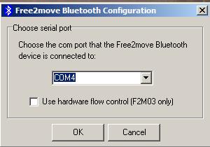
* Connect Bluetooth-Modul to !FlightControl (solder jumper on BT Adapter: '''S1:1-2 / S2:2-3''') * Connect Bluetooth-Modul to MK-USB (place jumper on MK-USB, solder jumper on BT Adapter: '''S1:2-3 / S2:1-2''') * Open program "Free2move Configuration Software" .____ * Choose COM Port from MK-USB and click '''"OK"''' .____ |
| Zeile 145: | Zeile 143: |
| '''Beispielansicht:''' <<BR>> {{attachment:usb1.jpg}} |
'''Example View:''' <<BR>> {{attachment:BT-AP10/usb1.jpg}} |
| Zeile 149: | Zeile 147: |
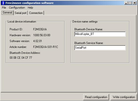
| * Nachdem das Modul erkannt wurde, öffnet sich das Programm. | * Once the module has been detected the program opens. |
| Zeile 151: | Zeile 149: |
| '''Beispielansicht:''' <<BR>> {{attachment:usb2.jpg}} |
'''Example View:''' <<BR>> {{attachment:BT-AP10/usb2.jpg}} |
| Zeile 155: | Zeile 153: |
| * Jetzt klickt man auf den Reiter '''"Connection"'''. * Den '''"Device Mode:"''' nun auf '''"Connecting (master)"''' umstellen und dann auf '''"Find device..."''' klicken. |
* Now you click on the tab '''"Connection"'''. * Change '''"Device Mode:"''' now to '''"Connecting (master)"''' and than click on '''"Find device..."''' . |
| Zeile 158: | Zeile 156: |
| '''Beispielansicht:''' <<BR>> | '''Example View:''' <<BR>> |
| Zeile 162: | Zeile 160: |
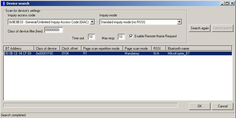
| * Bei "Enable Remote Name Request" einen Haken setzen , danach rechts auf "Search" klicken. * Im Fenster darunter werden nun alle erreichbaren Bluetoothverbindungen aufgelistet. * Das Bluetooth-Modul vom Kopter anklicken und mit "OK" bestätigen. |
* Place a checkmark at "Enable Remote Name Request" and click on "Search" on the right. * In the window below all accessible Bluetooth connections are listed. * Click on the Bluetooth-Module of the Kopter and click "OK" . |
| Zeile 166: | Zeile 164: |
| '''Beispielansicht:''' <<BR>> {{attachment:usb4.jpg}} |
'''Example View:''' <<BR>> {{attachment:BT-AP10/usb4.jpg}} |
| Zeile 170: | Zeile 168: |
| * Jetzt wird rechts unten die "Bluetooth address" angezeigt. * Das ganze mit "Write Configuration" abschließen. |
* Now the "Bluetooth address" will be displayed right below. * Finish all by clicking on "Write Configuration" . |
| Zeile 173: | Zeile 171: |
| '''Beispielansicht:''' <<BR>> {{attachment:usb5.jpg}} |
'''Example View:''' <<BR>> {{attachment:BT-AP10/usb5.jpg}} |
| Zeile 177: | Zeile 175: |
| * Fertig | * READY |
| Zeile 180: | Zeile 178: |
| Wird nun das KopterTool geöffnet sollte eine Verbindung zwischen den beiden Bluetooth-Modul aufgebaut und die übertragenen Daten angezeigt werden. | If you open now the !KopterTool a connection between both Bluetooth-Modules should be established and the transferred datas been displayed. |
| Zeile 187: | Zeile 185: |
| siehe auch: Selbstbau-Lösung: [[BTAP]] | see also: Do-it-yourself solution: [[BTAP]] |
Bluetooth-Modul |
Inhaltsverzeichnis
Shoplink
SET: Bluetooth-Module F2M03GXA + BT-Adapter + Parts: Shoplink
Bluetooth Adapter V1.0 (BT-AP)
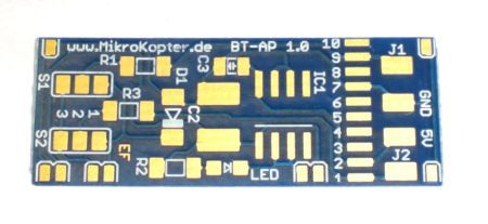
The board works as a power supply and level adjustment for the Bluetooth Module F2M03GXA.
This means that the BT module can be operated on a microcontroller with a 5V supply.
For an easier configuration the direction of RxD & TxD can be changed with solder jumper.
Instructions regarding the start up
![]() To avoid (self-inflicted) damages at the BT-Module necessarily proceed as follows:
To avoid (self-inflicted) damages at the BT-Module necessarily proceed as follows:
- First at all assemble the BT-Adapter PCB.
- Solder only the connection to the Bluetooth-Module if you have verified the correct function of the circuit.
Connect the BT-Adapter over a ribbon cable to the FlightCtrl.
It's enough if only the contacts #2 (+5V) and #7 (GND) been soldered.
For that reason you can use also the bigger pads.
The LED must flash and between the pins BT36 & BT37 you should measure 3,3V.
(See Schematic and assembly)
If that is OK you can solder the adapter to the module.
Assembly Bluetooth-Adapter and Bluetooth-Module
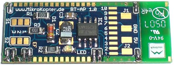
The very thin PCB-board (only 0,3mm) will be simply soldered to the bottom of the Bluetooth-Module.
![]() ATTENTION: Tantal capacitors have the mark at the anode (+). "marking=anode" is also described in the PDF-File of the Elkos.
ATTENTION: Tantal capacitors have the mark at the anode (+). "marking=anode" is also described in the PDF-File of the Elkos.
Tipp:
To connect the adapter board with the module you can use also single strands of a cable.
To the pins 1-10 (necessary are only the pins 1;2;7;9) you can solder very simple the ribbon cable:

The ribbon cable should be connected as shown.
If you connect it to the other side you disturb the Bluetooth antenna and also the receiving.
Connection to the Flight-Ctrl
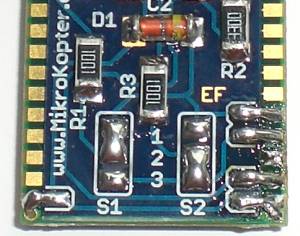
You need to set the solder jumper as follows:
Jumper
- S1: 1-2
- S2: 2-3
The complete Bluetooth-Module will be connected to the 10pin connector at the FlightCtrl.
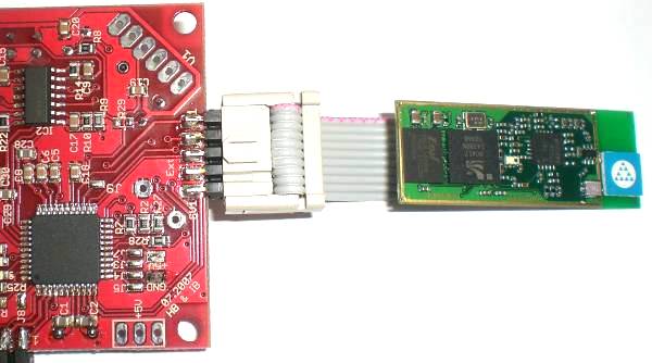
![]() If you use the GPS-System the module will be connected to the "Debug"-Port of the NaviCtrl .
If you use the GPS-System the module will be connected to the "Debug"-Port of the NaviCtrl .
Connecting to the PC
You need to set the solder jumper as follows:
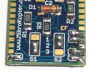
Jumper
- S1: 2-3
- S2: 1-2
Connecting to the MKUSB
The complete Bluetooth-Module will be connected to the MK-USB.
The jumper on the MK-USB need to be closed to supply the Bluetooth-Module with power.
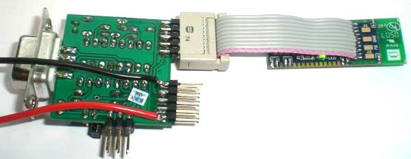
Connecting to the SerCon
Who still uses a Sercon can do this also.
Here you need to supply power to the PCB over the displayed spots +5V (red cable) and GND (black cable).
Schematic
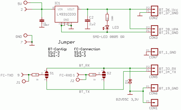
BT-AP10/Bluetooth-Adapter-PCB_V10_sch.pdf
Layout of placement
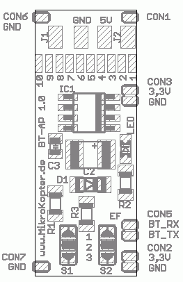
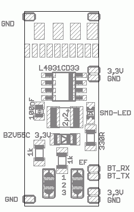
BT-AP10/Bluetooth-Adapter-Platine_V10_brd.pdf
Configuration
![]() NOTE The Bluetooth-Modules out of our shop are already programmed and tested.
NOTE The Bluetooth-Modules out of our shop are already programmed and tested.
The settings are:
Device Name: MikroKopter_BT
Password: 0000
Baud: 57600
Slave (for the connection to the MikroKopter)
After a successful assembly the Bluetooth-Module can be detected with those datas over a PC/Laptop or a cellphone with Bluetooth.
If you want to use two Bluetooth modules to get a greater range a second Bluetooth module need to be connected to the MK-USB.
(The manufacturer declares for the Bluetooth module F2M03GXA a range of ~350 mtr.)
Two settings for the Bluetooth Module need to be changed on the PC-side:
- The solder jumper need to be changed.
The module need to be set to Master .
With those settings you can pair both Bluetooth Modules with a secure connection.
Pairing two Bluetooth Modules
Two BT-Modules can be easily combined with each other via the configuration tool (pairen).
This can be done with the program "Free2move Configuration Software" Download
Step by Step Instruction:
Connect Bluetooth-Modul to FlightControl (solder jumper on BT Adapter: S1:1-2 / S2:2-3)
Connect Bluetooth-Modul to MK-USB (place jumper on MK-USB, solder jumper on BT Adapter: S1:2-3 / S2:1-2)
Open program "Free2move Configuration Software" .
Choose COM Port from MK-USB and click "OK" .
Example View:
- Once the module has been detected the program opens.
Example View:
Now you click on the tab "Connection".
Change "Device Mode:" now to "Connecting (master)" and than click on "Find device..." .
Example View:
- Place a checkmark at "Enable Remote Name Request" and click on "Search" on the right.
- In the window below all accessible Bluetooth connections are listed.
- Click on the Bluetooth-Module of the Kopter and click "OK" .
Example View:
- Now the "Bluetooth address" will be displayed right below.
- Finish all by clicking on "Write Configuration" .
Example View:
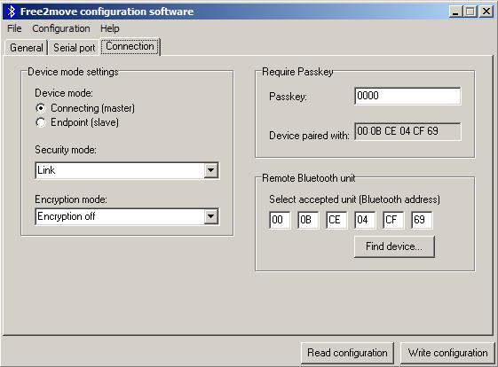
- READY
If you open now the KopterTool a connection between both Bluetooth-Modules should be established and the transferred datas been displayed.
Link
see also: Do-it-yourself solution: BTAP
- KategorieMK-Baugruppe/de

 Seite in
  Page en