|
⇤ ← Revision 1 vom 12.11.2014 14:11
Größe: 10809
Kommentar:
|
← Revision 2 vom 18.12.2014 13:30 ⇥
Größe: 10797
Kommentar:
|
| Gelöschter Text ist auf diese Art markiert. | Hinzugefügter Text ist auf diese Art markiert. |
| Zeile 67: | Zeile 67: |
| {{http://mikrocontroller.cco-ev.de/images/kopter/Mosfets.jpg}} | {{http://mc.mikrocontroller.com/images/kopter/Mosfets.jpg}} |
| Zeile 78: | Zeile 78: |
| {{http://mikrocontroller.cco-ev.de/images/kopter/Kommutierung.jpg}} | {{http://mc.mikrocontroller.com/images/kopter/Kommutierung.jpg}} |
| Zeile 85: | Zeile 85: |
| {{http://mikrocontroller.cco-ev.de/images/kopter/shunt.jpg}} | {{http://mc.mikrocontroller.com/images/kopter/shunt.jpg}} |
| Zeile 92: | Zeile 92: |
| {{http://mikrocontroller.cco-ev.de/images/kopter/ATMEGA8.jpg}} | {{http://mc.mikrocontroller.com/images/kopter/ATMEGA8.jpg}} |
Seite in deutsch |
See also: BL-Ctrl_2.0
Inhaltsverzeichnis
Information about the pre-populated brushless controlers can be found here: en/BL-Ctrl_V1_1
Brushless Ctrl (or Electronic Speed Controller, ESC) (General)
The Mikrokopter is powered by brushless motors.
![]() A manual for building and using the BL-Ctrl can be found under en/BL-Ctrl_Manual...
A manual for building and using the BL-Ctrl can be found under en/BL-Ctrl_Manual...
The advantages of such motors are :
- High efficiency and performance
- Less risk of interference as there are no brushess or gears.
- Numerous sources of motors with different power output and rpms per Volt.
However, to use such motors the direct current of the batteries has to be converted to an triphasic alternating current) with power output controled so that the speed of the motors can be accurately controled.There are numerous brushless speed controlers available on the market. However very few are available which can fulfill the special requirements: We need brushless controlers which can accept a new throttle value very rapidly (< 0.5ms) and implement it. In addition the controler has to have an I2C bus interface.
For this reason we have developed a reasonably priced brushless speed controler
The manual for building, the diagram, software, and partslist are all available in the download area [/de_mk/download.php#BL Downloadbereich] (still in German)...
Bare printed circuit boards (PCBs) and PCBs with surface mount devices (SMDs) premounted can be ordered in the Shop.
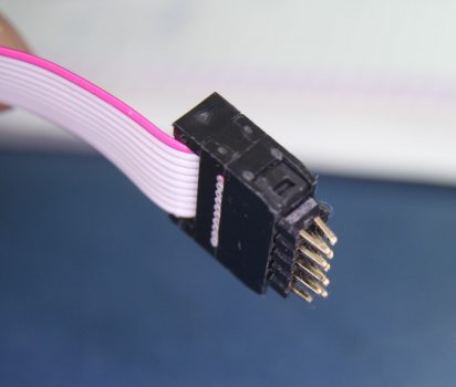
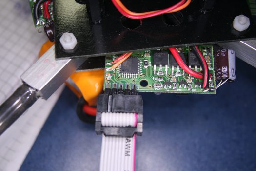
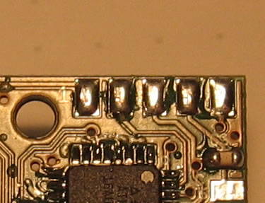
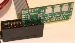
For programming these speed controlers you will need an ISP adapter such as SerCon. ISP is an abbrevaition for the hardware interface used between microcontroler and programmer.
We use these ESCs with e.g. ROBBE ROXXY 2815 or ROBBE ROXXY 2824-34 brushless motors.
- Technical Details
- Size 20 * 43mm
- BL-Ctrl Version 1.2: 10-12A Continuous power output approx. 160W
BL-Ctrl Version 1.2: Peak current: 20A -> Peak power output approx. 375W (max. several seconds)
BL-Ctrl Version 2.0: Peak current: 40A -> Peak power output approx. 650W (max. several seconds)
Controller: Atmel Atmega8 or Atmega168 (only BL-Ctrl_2.0)
- Power measurement and -limiting on the direct current side of the ESC
- Two LEDs (green: Okay and red: Error)
- Battery voltage measurement and low-voltage recognition
- The software is writen in C and the sourcode is available in the repository
- Several possibly input interfaces for throttle values (I2C, PWM, serial)
- One receive can be powerd from the 5V rail from the ESC (max. 50mA) (Note: you cannot power the flight controler or servos from these ESCs).
Possible interfaces:
- Asynchronous serial interface (either for throttle control or debugging)
- I2C (for high speed throttle control)
- PWM Signal (standard single channel output from an RC receiver) Principle of operation
Configurable by the I2C-bus using Koptertool -> the Koptertool can remain connected to the Navi or the FC (only BL-Ctrl_2.0)
Jumper to address the Addresses 1-4 and 1-8(only BL-Ctrl_2.0)
The control of brushlss motors is tri-phasic in groups of PWM pulses. The PWM frequency determines the hight of the phase-voltage (actually the arithmic mean of the voltage).
The phase voltage on the motor (as group of PWM pulses) determines the rotations per minute (RPMs) of the motor: a motor generates a countercurrent when turning (like a generator). the resultant RMPs will be the balance between current, coutercurrent and power output.
At any time 2 of the 6 FETs are operational to power the motor. The time of commutation (the time at which the 2 FETs must be switched off and the next two switched on to go to the next phase), is determined by voltage measurement (actually comparison) of the unpowered phase of the three motor wires. To do this the different analog comparators of the Atmega8 are used.
Power is measured by the voltage drop over a defined shunt on the PCB.
MOSFETs
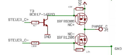
The poweroutput stage consists of an N-Channel and a P-Channel MosFet for each of the three phases. The P-Channhel Mosfet requires a transistor to be able to switch the gate potential over a controler output pin.
The 10A-MOSFETs from the MK Shop require no special cooling also in closed environment (27°C) under full load. But this depends on a clean and holohedral solder joint:
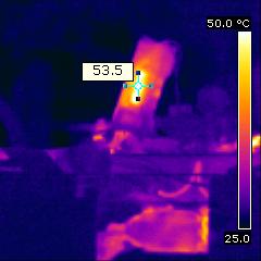
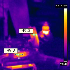
left NMOS, right PMOS
Recognition of the rotor position
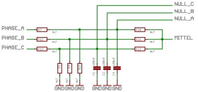
This simple part of the circuit allows measuring the position of the rotor in the brushless motor.
From the voltages of each of the motorphases a virtual star is calculated (averaging). The controler compares the filtered voltages of the phasses with the average voltage and uses this to calculate the timepoint for cummutation, which is the point in time at which the FET stage is switched to the next phase.
Power measurement
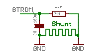
There is a shunt on the PCB, consisting of a wider copper trail which is lengthened a bit, similar to the layout in this drawing.
The voltagedrop over the shunt allows the controller to calculate the power used, and to reduce power if amperage is excessive. The software does not suddenly cut power, but gradually decreases it. This ensure that the aircraft does not suddenly drops out of the sky if the ESC is close to its maximum power output.
Microcontroler
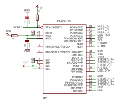
The Atmel Atmega8 is used as microcontroler.
It has some important features required for use in such speed controlers: the analog comparators with multiplexers. In addition it has serial interfaces and and an I2C interface integrated into the chip.
The Atmega8 is easy to program, requires limited peripherals and is fast enough for our required RPMs.
LEDs
After powering up the fully populated and soldered speed controler, and testing that the voltage over "J8" and "GND" is 5V. the LEDs will not be lighting up yet. Only after the ESCs have been programmed will the LEDs become operational and signal the following:
Both LEDs remain OFF: No power to the ESC...
Red and green LED ON: Receiver not connected or not receiving any signal (and therefore no control signals to the ESCs). Is the transmitter ON?
Green LED ON: The ESC is ready for use.
Green LED pulses ON/OFF: The ESC is receiving throttle values but the motor is not connected.
During programming both LEDs on the ESC wil be off. Only after programming has been completed and the ESC has reinitialised will the LEDs operate normally again.
In the BL-Ctrl V0.35 firmware a selftest has been implemented.
Different error states are tested on powering up. If an error is found the red LED will blink.
- 1 blinks: Phase A
- 2 blinks: Phase B
- 3 blinks: Phase C
- 4 blinks: Shunt is broken
If the Red LED does not blink, everything should be OK.
In addition the motorwindings will beep during the selftest. It is possible that the propellor might turn a bit as well, although without much power (your fingers won't be cut off, but SAFETY FIRST AT ALL TIMES nonetheless).
After initialisation a series of tones can be heard when the controler testes its endstages.
In case of errors the ESC will also be sending characters to the serial port that indicate which MosFet are at fault. To see these characters the ESC has to be connected to a computer with SerCon (or a similar serial interface adapter). The error codes are:
1: Short circuit Phase A ( against B ) -> ESC not ready
2: Short circuit Phase B ( against A ) -> ESC not ready
3: Short circuit Phase C ( against B ) -> ESC not ready
- 4: Mosfet NA- doesn't always shut off
- 5: Mosfet NB- doesn't always shut off
- 6: Mosfet NC- doesn't always shut off
7: Short circuit Phase C ( against A ) -> ESC not ready
- A: NA+ doesn't switch on
- B: NB+ doesn't switch on
- C: NC+ doesn't switch on
- a: NA- doesn't switch on
- b: NB- doesn't switch on
- c: NC- doesn't switch on
(Further informaton on the individual errors can be found on the page BL-Ctrl_Fehlerbeseitigung)(still in German)
- Advised Motors
The following motors have already been used successfully:
- The sequence of listing has no meaning!
ROXXY2815: For small (< 50cm diagonal motor to motor axis distance) and lightweight Mikrokopters. The ready to fly (RTF, take-off) weight should not significantly exceed 500 grams. Propellors : 8"x4 (i.e. x-Ufo sized)
ROXXY2824-34: For midsized (~ 50cm axis distance) Mikrokopter. The RTF weight should not be significantly more than 800 grams. Propellers: 10"x4,5 (e.g. GWS EPP1045)
ROXXY2827-35: For midsized (~ 50cm axis distance) Mikrokopters. The RTF weight should not be much above 1000 grams. Propellers: 10"x4,5 (e.g. GWS EPP1045)
- ... Firmware files
All firmware files, documents, and source coude can be find here:Downloads
Software update
The connection on the side of the MKUSB must be used.
See also: Update in the Koptertool
Files
Files here: Downloads
connecting the BL-Ctrl
