See also: en/MK-Okto
Inhaltsverzeichnis
MikroKopter – Bouwinstructies
Hoe converteer je een hoop onderdelen in een vliegende Mikrokopter? Hier vind je een aantal handige tips die van pas komen bij het bouwen van je MK.
Klik op de foto's om te vergroten.
MikroKopter Voor en na
Dit is een video over de assemblage.
Het frame
Het frame geeft de Mikrokopter zijn structurele integriteit.
Het moet voldoen aan de volgende eigenschappen:
- stijf (bestand tegen torsie en doorbuiging)
- licht
- afhankelijk van persoonlijke smaak: looks
Dit is een typische frame set voor een standaard Mikrokopter met een afstand van 40 cm tussen de motorassen. Het gewicht van het frame varieert - afhankelijk van het aantal gebruikte bouten - tussen de 100 en 110g.
De motorasafstand wordt bepaald door de diagionale afstand langs de armen van het frame. De kortste afstand tussen 2 naast elkaar gelegen motorassen is kleiner, nl: 40 / 1.4 = 28.5cm.
Het frame schilderen
Als het frame geschilderd wordt moet één van de armen een contrasterende kleur krijgen. Rood is een goede keuze.
Vooraleer je met schilderen begint moet het frame worden geschuurd en ontvet zodat de verf beter hecht.
Als je het frame niet wil schilderen kan je een van de armen ook overtrekken met een gekleurde krimpkous of deze anodised
Frame assembleren
Bovenaanzicht:
Onderaanzicht:
Opmerkingen:
De kleine gaatjes die zich aan de bovenzijde bevinden dienen om de elektromotoren te bevestigen
- De vier bouten aan de binnenzijde moeten van metaal zijn en met borgmoeren stevig worden vastgeschoefd. Deze bevestigingen zijn cruciaal voor de structurele stijfheid van het frame en je Mikrokopter.
De FlightCtrl module wordt later met plastic afstandsbussenwill bevestigd aan de bovenzijde van het frame
- De acht bouten aan de buitenzijde houden de armen van het frame in positie. De moeren worden aan de onderzijde bevestigd.
Video of frame assembly (8,8MB)
Elektronica
- De elektronica en de algoritmes die de processors sturen zijn de centrale componenten van een Quadrocopter. Een dergelijk toestel in principe onbestuurbaar. Enkel door gebruik te maken van een snelle motorsturing die reageert op data die afkomstig is van verschillende sensoren blijft een Quadrakopter in de lucht.
De elektronicacomponenten zijn:
FlightControl -> "Hoofdcontrole-eenheid" voor de berekening van de besturingsgegevens.
BL-Ctrl -> snelle controle-eenhyeid voor de aansturing van de Bl Motors
Ontvanger-> elektronische interface met de afstandsbesturing (en dus de piloot)
LiPo-batterij-> stroomvoorziening
FlightCtrl
Op het voorbestukte FlightCtrl bord, dienen nog een aantal componenten te worden gesoldeerd vooraleer deze volledig afgewerkt is. Voorbestukte borden zijn over het algemeen rood van kleur.
De term FlightCtrl wordt soms afgekort tot "FC".
Bord voor en na de assemblage van de ontbrekende componenten.
De assemblagepositie van de FC is bepalend voor de goede werking:
- de pijl naast de schakelaar moet in de richting wijzen van de gekeurde arm (BL-Ctrl number 1)
- bord moet perfect horizontaal opgelijnd worden
- de processor moet zich bovenaan bevinden
Video of assembly of the remaining parts (21.3MB)
Further information for the assembly of the FC
BL-Ctrl
De Bl-Ctrl werd speciaal ontwikkeld voor quadrocopters met Bl Motoren.
Compared with typical Brushless controllers, it has a fast data bus to the FC (I2C) which results in a spontaneous regulation of motor setpoints. Normal Brushless controllers can not be used.
The Bl-Ctrl’s are designated an address of 1-4 via a solder jumper.
Address choice
On the Bl-Ctrl V1.2, motor addresses are set using a solder jumper on the board.

They are set in the following way:
Address (Motor) |
1-2 |
2-3 |
1 (front) |
open |
open |
2 (back) |
open |
closed |
3 (right) |
closed |
open |
4 (left) |
closed |
closed |
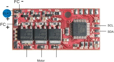
- On the preassembled Bl-Ctrl V1.2, the supplied Electrolyte Capacitor will have to be soldered on:
NaviCtrl
Wiring
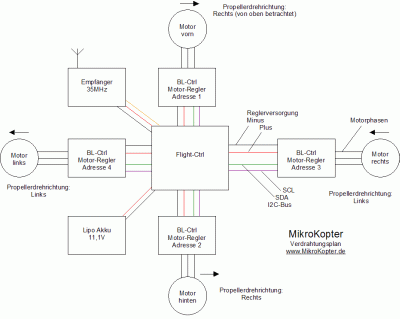
This Overview diagram shows amongst other things the wiring, addresses and positions of the Motor Controllers aswell as the rotational direction of the propellers: 
Wiring
Wire Tree
Start by preparing the DC cables for the DC power supply.
The wire tree is prepared using a thick primary wire (approx. 10cm), onto which 4 splitting lines (approx 12cm) are soldered. The joint should be secured with plenty of solder. Following this, use shrink tubing or electrical tape to insulate the joint.
The splitting lines (Plus and Negative) are connected to the four Bl-Ctrl’s.
Things to note:
- Plus and Negative must under no circumstance be exchanged!
- Red = Plus
- Black = Minus
- The bare wires should not be exposed to far in order to avoid electrical shorts
- The wire ends need to be well tined to ensure that no copper strands are freely exposed
Motor Lines
The motor lines connect the motor with the output of the Bl Ctrl. The Bl Motors require a so called rotary field. For this reason three lines are required.
For clarity we use three different colours. The rotary directing of the motors can be changed by switching any two of the three lines. It is therefore not important at this stage in what way these three lines are connected.
The lines should be approx. 22cm long. They will be shortened later.
I2C-Dataline to the Bl Controllers
The I²C Bus provides the communication between the Bl Ctrl’s and the FC.
It consists of two signals
- SCL (Tact) shortened "C" (in this case the red signal line)
- SDA (Data) shortened "D" (in this case the black signal line)
Each "C"-Line (Clock) of the four Bl Ctrl’s needs to be connected to the "C"-Pad of the FlightCtrl.
Each "D"-Line (Data) of the four BL Ctrl’s needs to be connected to "D"-Pad of the FlightCtrl.
It has proven useful to solder and bend the I2C lines as shown in the pictures in order to avoid them tearing off during any mechanical stress.
Attachment of the Receiver to the FC
Connect the small receiver Cable to the FC. On the FC you will have the corresponding colors (Brown/Red/Orange AND GN/+5/PPM)
![]() Attention Spektrum (DX7) Users see more details about the Digital Transmitter Spektrum DX7
Attention Spektrum (DX7) Users see more details about the Digital Transmitter Spektrum DX7
Attachement of the supply lines to the FC
The Wire Tree to the Bl Ctrl’s and the Power line is now attached to the FC.
The Battery cable utilises the male battery connector(Description: DEANS ) (is labled with + and - ) and an approx. 15cm long connection line. The contacts on the battery connector must be protected against electrical shorts using shrink tubing.
The Plus of the battery lines is soldered onto the Pad at the switch (towards middle of the board). The Plus of the wire tree is soldered onto the pad on the middle of the switch connections.
The two Minus lines are soldered onto the solder pad facing towards the near corner of the switch.
Attachement of Lighting systems
At least the leading frame arm should be clearly marked for orientation when flying. At long distance this can be nicely achieved using a lighting system.
The light strips need to be supplied by a 12V source. The easiest way to achieve this is to connect them via a thin line to the power supply of the front BL Ctrl (Number 1). In this case a 4-5cm line length is sufficient.
Later on, the lighting, together with the frame arm needs to be covered with shrink tubing to avoid electrical shorts.
Attachement of the the Buzzer
Initially the buzzer used to be located directly on the FC. However, due to its strong magnetic field we will isolate is from the start by placing it at the end of one of the frame arms.
Otherwise, the buzzer will interfere with the electronic compass (MK3Mag), which may be added as a later option.
Important: The Plus of the buzzer (marked) must be connected to the + on the FC board
Instalment of electronics into the frame
The entire electronics should now look like this:
Dry test of the electronics
The basic functions of the electronics can already be tested at this stage. There is no need to connect motors for this.
Procedure:
- Connect Receiver (with crystal) using the output for the sum signal (channel 1 on the DSL4TOP)
- Spread out electronics so that no electrical shorts can occur.
- Connect 12V (from a powerpack – this is safer in case an electrical short occurs. Connect the FC and BL Ctrl's to the same powerpack to ensure correct operation of the I2C Bus.)
- Turn on Transmitter
- Turn on FC
Control:
- The green LEDs on the BL Ctrl’s must be on. This indicates that they have a power supply
- The red LED’s on the Bl Ctrl’s must be off. This shows that the I2C-Bus works.
- The green LED on the FC must be on to show that it has a power supply.
- The red LED on the FC is off when it has a signal from the receiver.
The Buzzer is off when; The FC has a receiver signal, the I2C is ok and the supply voltage is > 9.6V
- The Buzzer beeps when the transmitter is turned off.
- One may attempt to start the motors (which are not connected). This results in a flickering of the green LED’s and the red LED’s stay off. (To start = Throttle at zero and rudder full right)
Assignment of the Bl Ctrl’s
The addressed BL-Ctrl’s must now be placed as follows:
Motor |
Position |
#1 |
front |
#2 |
back |
#3 |
right |
#4 |
left |
Rule of Thumb: Controller #3 at 3 o’clock
The BL Ctrl’s can be threaded through the middle of the center plates (the corner bolts may have to be loosened for this). Following this the motor cables should run outwards and the supply lines towards the center.
Video of shrink tube insulating of the Bl Ctrl’s (5MB)
Instalment of Flight-Ctrl
A directional arrow is located in a corner on the top side of the Flight Control. It is important that this arrow MUST point forward i.e. towards motor 1!
The arrow is marked by a red square in the following illustration:
Instalment and mounting of Motors und Propellers
The motor lines should be encased in heatshrink (or at least secured well using cable ties). On the rear arm, the buzzer may be attached at the same time using the heat shrink.
The colour of the frame arms will last longer if they are encased in shrink tubing.
The Motors include connectors.
The use of these connectors has the advantage that the motors can (if required) be quickly exchanged or rotary directions changed by switching two of the three lines.
Mounting of the Battery
In some cases a female Deans-Connector needs to be attached to the Battery. The plug is labled with Plus and Minus.
Again, ensure that soldered points are well tinned and protected against electrical shorts using shrink tubing.
![]() Under no circumstances short circuit the Battery Lines!
Under no circumstances short circuit the Battery Lines!
The Battery is secured using two double sided hook and loop (Velcro) tapes(Photo). The Hook and Loop bands should be attached to the centre of the frame using cable ties.
Tip: The Battery can be mounted more securely by sticking Velcro tape onto it.
Opperation and Flying
Instructions – switching on - calibrating etc
It is defiantly worth taking a look at the FlugSchule (Flight School).
Video- Flight School by Robert-t
![]() Under constructions: Quite a few more things to be added here
Under constructions: Quite a few more things to be added here
 Seite in
  Pagina in
  Page en