FlightCtrl V2.1 |
See also: FlightCtrl overview
Inhaltsverzeichnis
Flight Ctrl V2.1
Vue supérieure
Prise Molex pour le raccordement au Circuit Imprimé de Distribution (Okto)
Connexions de haut en bas:
1 - Masse (FC et buzzer)
2 - + Buzzer
3 - I2C Bus (D)
4 - I2C Bus (C)
5 - +12V (tension de la batterie)
Lorsque vous utilisez ce câble, vous ne pouvez pas utiliser l'interrupteur de la FC. Le MK est alors allumé en branchant la lipo (Ce qui est de toute façon habituel pour plus de 4 moteurs )
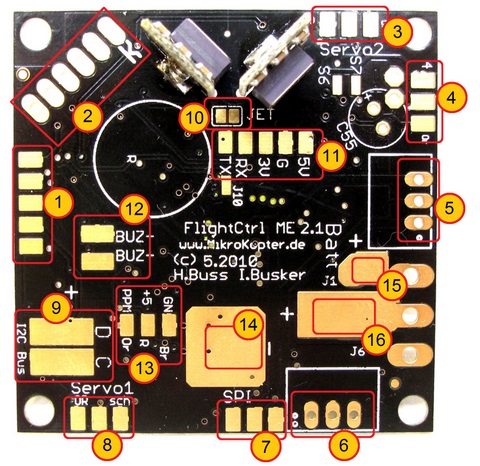
Vue inférieure

1 - bloc connecteur à 2x5 broches (MK-USB ou NaviCtrl)
2 - Capteur altimétrie (repère coté droit gyro)
3 - bloc connecteur à 2x3 broches (Servo2 / Servo3)
4 - bloc connecteur à 2x3 broches (Servo4 / Servo5)
5 - Convertisseur DC / DC RECOM 5V (alimentation FC ME)
6 - Convertisseur DC / DC RECOM 5V (alimentation Servos)
7 - bloc connecteur à 2x3 broches(NaviCtrl)
8 - bloc connecteur à 2x3 broches (Servo1 / Sorties J16/J17)
9 - connexions I2C (D/C) pour les BL-Ctrl.
10 - JET (à ponter pour l'utilisation du canal data d'un récepteur Jeti)
11 - bornier (5V, G, 3V, RX, TX)
Avec un récepteur (satellite) Spectrum:
- le câble du Rx Spectrum devra être soudé (bornier N°11) avec Orange-3V, Noir-G, Gris-RX avec le pont «JET» N°10 ouvert.
Avec un récepteur (satellite) Jeti:
- le câble PPM sera soudé au bornier N°13, avec « JET » ponté N°10,
- le canal de données du récepteur sera soudé au " RX " du bornier N°11
12 - Connexion Buzzer (BUZ-/BUZ+) (inutilisées si Molex)
13 - Connexion PPM récepteur (GN-marron, +5-rouge, PPM-Orange)
Inutilisées avec la prise Molex (Hexa & Octo ou mini-CID):
- 14 - Connexion négatif (moins) alimentation
- 15 - Connexion positif (plus) alimentation (utilisation de l'interrupteur)
- 16 - Connexion positif (plus) alimentation (Sans interrupteur)
Infos supplémentaires sur la f FC2.0
Connexions
(Excepté pour le connecteur Molex blanc sur la FC2.1, les connecteurs sont identiques à la FC2.0)
Connexion SV1
Connexion SV2:
Rangée supérieure (Sorties)
Pin1: 100mA Sortie (négatif) NPN Collecteur ouvert p.e. pour les LEDs. Paramétrable dans Koptertool avec J16.
Pin3: +5 Volts servo
Pin5: 100mA Sortie (négatif) NPN Collecteur ouvert p.e. pour les LEDs. Paramétrable dans Koptertool avec J17.
Rangée inférieure: Sortie Servo Tangage
Pin2: Sortie signal Servo1 (Pour la stabilisation en tangage de la nacelle) (Paramétrable dans Koptertool)
Pin4: +5 Volts servo
Pin6: GND / Négatif
Nota: La sortie servo est inactive tant que l'initialisation FC n'a pas été faite (Manche gaz maintenu en haut à gauche jusqu'à l'audition du buzzer x setting et diode verte/FC)).
Connexion SV3:
Rangée supérieure (Servo 3)
Pin1: Sortie signal Servo3
Pin3: +5 Volts servo
Pin5: GND / Négatif
Rangée inférieure: Sortie Servo Roulis
Pin2: Sortie signal Servo2 (paramétrable Koptertool)
Pin4: +5 Volts servo
Pin6: GND / Négatif
Connexion SV4:
Rangée supérieure (Servo 5)
Pin1: Sortie signal Servo3
Pin3: +5 Volts servo
Pin5: GND / Négatif
Rangée inférieure: (Servo 4)
Pin2: Sortie signal Servo5
Pin4: +5 Volts servo
Pin6: GND / Négatif
Connexions Récepteur
Please note, that you have to choose the right receiver in the settings under "Channels".
Récepteur Standard PPM
P.e.
Connection:
PPM - sum signal |
||
Pad |
Function |
Cable color |
GN |
GND/Minus |
Black |
+5 |
Plus 5V |
Red |
PPM |
data connection |
Orange |
Click to enlarge the image |
||
Récepteur Satellite Spektrum
L'alimentation 3,0V et la liaison data RxD pour ces récepteur sont disponible sur la face inférieure: Bornier N°13
Connection:
2nd serial port connection |
||
Pad |
Function |
Cable color |
G |
GND/Minus |
Black |
3V |
Plus 3V |
Orange |
RX |
data connection |
Gray |
Click to enlarge the image |
||
Voir aussi: Spektrum
Récepteur Satellite Jeti
La diode externe (nécessaire avec la FC-Version 2.0) est intégrée sur la FC 2.1 il suffit de souder le pont N°10
Connection:
PPM - sum signal + Telemetry |
||
Pad |
Function |
Cable color |
GN |
GND/Minus |
Black |
+5 |
Plus 5V |
Red |
PPM |
data connection |
Orange |
RX |
Telemetry connection |
User defined |
JET |
solder bridge for Telemetry |
- |
Click to enlarge the image |
||
Voir aussi: JetiDuplex
HoTT Receiver
Since Software version V0.86
The HoTT receiver will also connected on the PPM and RX pads of the FlightCtrl. To send the telemetry a solder bridge on "JET" is needed.
More informations about the HoTT-System you can find here: HoTT
Connection:
PPM - Sum signal + Telemetry |
||
Pad |
Function |
Cable color |
GN |
GND/Minus |
Black |
+5 |
Plus 5V |
Red |
PPM |
data connection |
Orange |
RX |
Telemetry connection |
User defined |
JET |
solder bridge for Telemetry |
- |
Click to enlarge the image |
||
Futaba S.Bus Receiver
Since Software version V0.88 / FlightCtrl V2.1
A S.Bus receiver can be connected with a signal-inverter to the FlightCtrl.
The needed Signal-Inverter you can get here: Shoplink
Connection:
2nd serial port connection |
||
Pad |
Function |
Cable color |
5V |
Plus 5V |
Red |
G |
GND/Minus |
Black |
RX |
data connection |
Orange |
Click to enlarge the image |
||
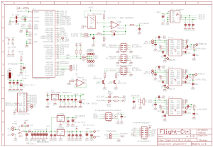
Schéma de câblage
![]() L'utilisation des logiciels Mikrokopter est autorisée exclusivement sur les produits originaux Mikrokopter.
L'utilisation des logiciels Mikrokopter est autorisée exclusivement sur les produits originaux Mikrokopter.
Évolution matérielle depuis la Version V2.0
- Le processeur à le double de capacité mémoire (ATMEGA1284P)
- Connecteur Molex pour simplifier la liaison avec les CID (Octo seulement 07/10)
- Régulateur intégré (3v) pour p.e. les satellites spectrum
Diode intégrée activable par soudure pour la liaison retour JetiBox
- Résistance ajustable pour calibrer l'altimètre jusqu'à 2000-3000m (ndlt: où ca ?)
- Adaptation de la plage de mesure du capteur de altimétrique : (selon la situation atmosphérique) jusqu'à environ 2000-3000m (depuis la v0.80g)
- Résistance d'ajustement pour l'I2C.
- Diode de protection pour la sortie buzzer.
- Très belle livrée Noire !
Fourni à présent avec la V2.1 (en comparaison de la V2.0)
Un capteur d'altimétrie MPX4115A en Std
Deux régulateurs 5v(RECOM ou équivalant) en Std (1 Pour la FlightCtrl + 1 pour les Servos et autre)
- L'interrupteur n'est plus fourni en Std et devra être commandé séparément si nécessaire.
Divers
- Le bootloader de la FC2.1 n'est pas publique et ne peut être lu - Merci à nos "bons amis" en chine.
Un processeur AtMega1284 avec le bootloader préloadé est disponible sur le shop MK•DE
- En aucune circonstance il n'est possible de programmer ou effacer l'ISP avec un programmeur d'Atmel
Développement Logiciel
Pour le nouveau Processeur-AtMega1284, le développement du logiciel nécessite cela: WinAVR-20060421 Compiler, et également les patch spéciaux de H&I.
- De plus, dans le fichier "makefile" du projet, choisir le type de processeur avec la commande "MCU = atmega1284p".
Impressum
Traduction française: MK-FR•info


