Inhaltsverzeichnis
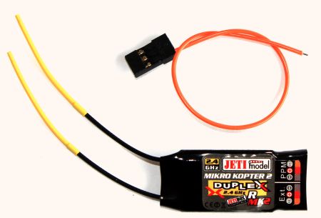
Jeti receiver RMK2
There is a special MikroKopter-Edition for Jeti-Duplex

This receiver doesn't have to be modified for the use in the MikroKopter.
Also it allows the telemetry to the JetiBox
Connection to the FC V2.1
- Bridge at (10) "JET"
- orange data cable to "Rx"
- Servo cable to PPM
See also: JetiDuplex
Binding
Transmitter and receiver must be paried. So they now which receiver has to listen to which transmitter.
- put the binding plug into the RMK (EXT) (red plug with a bridge)
Switch on the MikroKopter (or power the RMK via 5V on the PPM-Input)
- Switch on the transmitter
The Jeti-Transmitter should beep now to show the binding was finished
Update
If a software update is nessecary, it can be updated: JetiUpdate
Fail safe
In case of transmission loss, the RMK-Receiver deactivates the output signal and the FC detects tis signal loss. This is default.
setting fixed channel outputs for Fail safe
It is possible to activate a fail safe in these receivers.
That means, that the RMK-Reciever generates own channel outputs in case of signal loss.
![]() Depending on these settings, the FC doesn't recognise that there is a loss of transmission and stays in the air!
Depending on these settings, the FC doesn't recognise that there is a loss of transmission and stays in the air!
![]() Select the channel settings carefully to avoid that the MK is out of control!
Select the channel settings carefully to avoid that the MK is out of control!
![]() Select a low Value for the throttle-channel to make sure the MK goes down.
Select a low Value for the throttle-channel to make sure the MK goes down.
Activating the fail-safe:
SW-Version 1.22
Notice: If you use fail safe with this version, you have only 8 channels to use!
The transmitter and receiver has to be on. Use the JetiBox for the Menus
- Go to the menu of the Receiver (RX) (go Right after switch on)
Down -> "measure or setting"
Right -> "Main Setting"
Down -> "PPM Output mode"
Left -> change in "Computed" (see Tip)
Down -> "Signal Fault". This means that the signal switches off in case of transmission loss. In that case the FC detects this signal loss correct.
Right to "Fail Safe" -> now the signals are computed in case of signal loss
- go back (Up, up,...) to "measure or setting"
- Right, right to "out Pin set"
Down -> select the channel (Y1...Y8 are the channels 1-8)
Down, Down, Down,Down, Down, Down -> "Fail Safe"
-> change the Value here ("0.80ms" are 0, 2.20ms are 250)
- continue in menu "out Pin set" and change to the next channel
SW-Version 2.01
Notice: If you use fail safe with this version, you have up to 16 channels to use!
Step 1 |
Step 2 |
Step 3 |
Go to the menu of the |
Down to "Measure Or Setting" |
Right to "Main Setting" |
Step 4 |
Step 5 |
Down to |
chosse the numbers of |
Step 6 |
Step 7 |
Down to "PPM Output mode" |
Change into "computed"" |
Step 8 |
Step 9 |
Down to "Signal Fault" |
Right to "individual set" |
Step 10 |
Step 11 |
Now back up to |
and right to "Out Pin Set" |
Step 12 |
Here you can chose the channel you will use for |
Down to "Set Output Pin" |
Step 13 |
Step 14 |
Down to "Signal Fault Yx" |
change into "fail save" |
Step 15 |
Here you can set the |
Down to "Fail Save Yx" |
controll the "Fail Save" function
To control the function start the KopterTool and open "Channels". Then switch off the transmitter.
The "Fail Safe channel(s)" must change into the level that you use under "Fail Safe".
Tip if you don't have the menus in "Out Pin Set": The output mode must be changed to "computed" ("main setting" -> "PPM output mode")
![]() Check the fail-safe channel outputs in the Koptertool before starting.
Check the fail-safe channel outputs in the Koptertool before starting.

 Seite in
  Page en