|
Größe: 3202
Kommentar:
|
Größe: 5327
Kommentar:
|
| Gelöschter Text ist auf diese Art markiert. | Hinzugefügter Text ist auf diese Art markiert. |
| Zeile 1: | Zeile 1: |
| [[TableOfContents]] | <<TableOfContents>> |
| Zeile 3: | Zeile 3: |
| == Introduction == | = Introduction = |
| Zeile 6: | Zeile 6: |
| [[BR]] | <<BR>> |
| Zeile 9: | Zeile 9: |
| You'll need two XBee modems. They come in 3 different antenna flavors. | You'll need two XBee modems. They come in 3 different antenna flavors. Below are listed some modules which operate in the 900Mhz range but there are other frequencies available including 2.4Ghz. |
| Zeile 11: | Zeile 11: |
| * XBee Pro 900 RPSMA - '''''This is the one most folks will use.''''' | * XBee Pro 900 RPSMA |
| Zeile 23: | Zeile 23: |
| [[BR]] | <<BR>> |
| Zeile 31: | Zeile 31: |
| [[BR]] | <<BR>> |
| Zeile 39: | Zeile 39: |
| [[BR]] | <<BR>> |
| Zeile 45: | Zeile 45: |
| . [[BR]] | . <<BR>> |
| Zeile 51: | Zeile 51: |
| [[BR]] The connection to the MK : | <<BR>> The connection to the MK : |
| Zeile 63: | Zeile 63: |
| attachment:xbee.jpg | {{attachment:xbee.jpg}} |
| Zeile 65: | Zeile 65: |
| [[BR]] | <<BR>> |
| Zeile 67: | Zeile 67: |
| attachment:xbeeboard.jpg | {{attachment:xbeeboard.jpg}} |
| Zeile 70: | Zeile 70: |
| [[BR]] | <<BR>> |
| Zeile 74: | Zeile 74: |
| [[BR]] Use the XCTU program to do any configuration you need, as well as testing the XBees. | <<BR>> Use the XCTU program to do any configuration you need, as well as testing the XBees. |
| Zeile 77: | Zeile 77: |
== Configuration of XBee Pro 2 modules == Setting up Xbee Pro 2 modules for plain point-to-point UART operation is a little more complicated. I got this working with the sparkfun regulator board, one sparkfun USB explorer board and two XBee pro Series 2 modules (all order via http://tinkersoup.de). Works flawless and fast for me. Use X-CTU (http://www.digi.com/support/kbase/kbaseresultdetl.jsp?kb=125) and acces via 9600 8,N,1 the first time. Check if you can connect the modules properly first using the test button on the main screen of the tool. You have to configure one module as "COORDINATOR" and the other as "ROUTER" and "hardwire" both modules to get maximum throughput. Go to the Modem Configuration tab and select the appropirate function set. Settings for the coordinator module: * Function Set = "ZNET COORDINATOR 2.5 AT" * PAN ID = select one freely but make sure both modules use the same * DH = SH value the router module * DL = SL value of the router module * BD = 57600 Settings for the router module: * Function Set = "ZNET 2.5 ROUTER/END DEVICE AT" * PAN ID = select one freely but make sure both modules use the same * DH = SH value the coordinator module * DL = SL value of the coordinator module * BD = 57600 Change the settings for both modules accordingly and press the write button. If you like you can update the firmware as well. After a succesful write you get an error message because X-CTU wants to connect to the module with 9600 baud which doesn't work anymore because you changed the value to 57600. Go back to the PC Settings tab and change Baud to 57600 and re-read the settings in the Modem Configuration tab. If you fire up both modules now, one to FC or NC debug and one to your PC via USB the RX/TX DIN/DOUT should start blinking and the RSSI LED should light up. Start MKTool and see if it works. I figured out the I can't access the the USB-connected module via X-CTU if both modules are paired. I have to shut down one of them first. |
|
| Zeile 81: | Zeile 117: |
| /!\ ToDo: | http://plischka.at/Funk_XBEE.html |
| Zeile 83: | Zeile 119: |
| ---- . KategorieEnglish ---- KategorieEnglish |
KategorieEnglish |
Inhaltsverzeichnis
Introduction
The XBee is a wireless modem that can be used to connect MK Tools running on a laptop to the Flight or Navi Controller on the Mikrokopter. This can be useful for data logging sensor data, making real-time poti adjustments, and for conducting waypoint navigation.
Materials
You'll need two XBee modems. They come in 3 different antenna flavors. Below are listed some modules which operate in the 900Mhz range but there are other frequencies available including 2.4Ghz.
- XBee Pro 900 RPSMA
http://www.sparkfun.com/commerce/product_info.php?products_id=9099
- XBee Pro 900 wire
http://www.sparkfun.com/commerce/product_info.php?products_id=9097
- XBee Pro 900 U.FL
http://www.sparkfun.com/commerce/product_info.php?products_id=9098
- U.FL to SMA adapter
http://www.sparkfun.com/commerce/product_info.php?products_id=9145
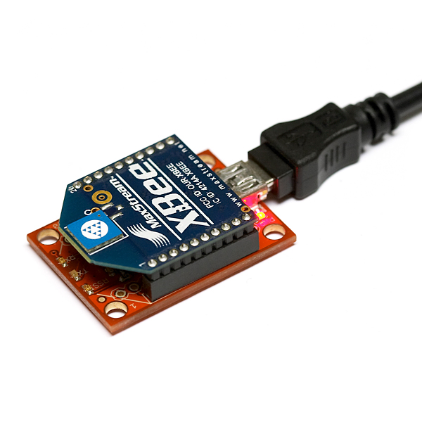
You also need two XBee adapters. One needs to the the USB version, because you just plug that into your computer, and fire up MK-Tool.
You can also use the USB version for the MK end, though it's more expensive, and slightly heavier than the "regulated" version which lacks the USB and FTDI stuff. You might have to jumper across a diode on the board as well, since it doesn't play nice with the diode in place.
If you're only going to buy two adapters, I'd recommend getting two of the USB versions, since you can use them to test the XBee modems on your computer. If you want more than 2 adapters, then you could get the cheaper ones.
- XBee USB Adapter
http://www.sparkfun.com/commerce/product_info.php?products_id=8687
- XBee "Regulated" Adapter
Here is another alternate regulator for inside the MK.
http://www.droids.it/990_001.html
Installation
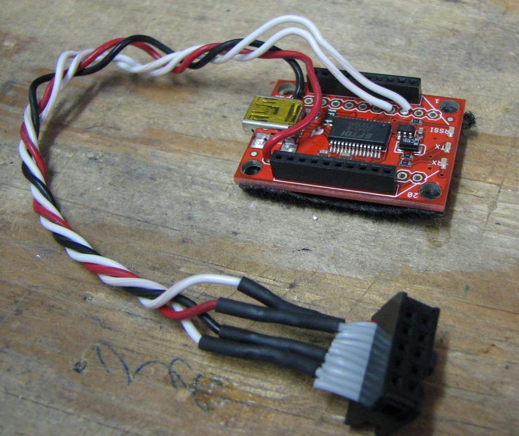
Each XBee modem plugs directly onto the XBee adapter. The Xbee adapter will be used on one end to connect to the computer via USB. On the Mikrokopter side, several wires need to be soldered onto the Xbee adapter so the adapter can be connected to the Flight or Navi controller. Using a 10-pin ribbon cable like the ones included with the Mikrokopter boards will simplify the installation a great deal. If you don't have spare ribbon cable, you can add one of these to your order:
http://www.sparkfun.com/commerce/product_info.php?products_id=8535
The connection to the MK :
MK FC or Navi-board.....- XBee
Pin 1..........................- Pin 2 (DOUT)
Pin 2..........................- 5V connection on XBee USB adapter board
Pin 7..........................- Pin 10 (GND)
Pin 9..........................- Pin 3 (DIN)


Configuration of the Xbee modules
Configure XBee for 57600 baud.
Use the XCTU program to do any configuration you need, as well as testing the XBees.
http://www.digi.com/support/productdetl.jsp?pid=3352&osvid=57&s=316&tp=5
Configuration of XBee Pro 2 modules
Setting up Xbee Pro 2 modules for plain point-to-point UART operation is a little more complicated. I got this working with the sparkfun regulator board, one sparkfun USB explorer board and two XBee pro Series 2 modules (all order via http://tinkersoup.de). Works flawless and fast for me.
Use X-CTU (http://www.digi.com/support/kbase/kbaseresultdetl.jsp?kb=125) and acces via 9600 8,N,1 the first time. Check if you can connect the modules properly first using the test button on the main screen of the tool.
You have to configure one module as "COORDINATOR" and the other as "ROUTER" and "hardwire" both modules to get maximum throughput. Go to the Modem Configuration tab and select the appropirate function set.
Settings for the coordinator module:
- Function Set = "ZNET COORDINATOR 2.5 AT"
- PAN ID = select one freely but make sure both modules use the same
- DH = SH value the router module
- DL = SL value of the router module
- BD = 57600
Settings for the router module:
- Function Set = "ZNET 2.5 ROUTER/END DEVICE AT"
- PAN ID = select one freely but make sure both modules use the same
- DH = SH value the coordinator module
- DL = SL value of the coordinator module
- BD = 57600
Change the settings for both modules accordingly and press the write button. If you like you can update the firmware as well. After a succesful write you get an error message because X-CTU wants to connect to the module with 9600 baud which doesn't work anymore because you changed the value to 57600. Go back to the PC Settings tab and change Baud to 57600 and re-read the settings in the Modem Configuration tab.
If you fire up both modules now, one to FC or NC debug and one to your PC via USB the RX/TX DIN/DOUT should start blinking and the RSSI LED should light up. Start MKTool and see if it works.
I figured out the I can't access the the USB-connected module via X-CTU if both modules are paired. I have to shut down one of them first.
Content Credit
Rusty (13brv3)
