
|
Größe: 8357
Kommentar:
|
Größe: 8506
Kommentar:
|
| Gelöschter Text ist auf diese Art markiert. | Hinzugefügter Text ist auf diese Art markiert. |
| Zeile 1: | Zeile 1: |
| ||<tablewidth="385px" tablestyle="text-align: center;"bgcolor="#ffffa0"> {{http://mikrokopter.de/images/deu.gif}} Page in [[FlightCtrl_ME_2_1|German]] ||<bgcolor="#ffffa0"> {{http://mikrokopter.de/images/fra.gif}} Page en [[fr//FlightCtrl_ME_2_1|français]] || | ||<tablewidth="520px" tablestyle="text-align: center;"bgcolor="#ffffa0"> {{http://mikrokopter.de/images/deu.gif}} Seite in [[FlightCtrl_ME_2_1|deutsch]] ||<bgcolor="#ffffa0"> {{http://mikrokopter.de/images/fra.gif}} Page en [[fr/FlightCtrl_ME_2_1|français]] ||<#ffffa0>Страница [[ru/FlightCtrl_ME_2_1|русском]] || |
| Zeile 8: | Zeile 8: |
| == Top Side== {{attachment:FC2-1-1.jpg}} |
== Top Side == {{http://gallery.mikrokopter.de/main.php?g2_view=core.DownloadItem&g2_itemId=76296&g2_serialNumber=2}} |
| Zeile 13: | Zeile 14: |
| . Connections from top to bottom:<<BR>> 1 - +12V <<BR>> 2 - I2C Bus (C)<<BR>> 3 - I2C Bus (D)<<BR>> 4 - + Buzzer<<BR>> 5 -Ground (GND FC and Buzzer)<<BR>><<BR>> | . Connections from top to bottom:<<BR>> 1 - Ground (GND FC and Buzzer) <<BR>> 2 - + Buzzer<<BR>> 3 - I2C Bus (D)<<BR>> 4 - I2C Bus (C)<<BR>> 5 - +12V<<BR>><<BR>> |
| Zeile 22: | Zeile 28: |
| == Bottom Side== | == Bottom Side == |
| Zeile 25: | Zeile 31: |
| 1 - 10pin connector for MK-USB or NaviCtrl connection<<BR>> 2 - Pressure Sensor (cut out of sensor connector points to the right)<<BR>> 3 - 6pin connector for servo 2 and Servo 3<<BR>> 4 - 6pin connector for servo 4 and servo 5<<BR>> 5 - DC/DC voltage regulator 5v Recom for Flight Controller<<BR>> 6 - DC/DC voltage regulator 5v Recom for servos<<BR>> 7 - 6pin connector for NaviCtrl<<BR>> 8 - 6pin connector for servo 1 and switchable J16/J17 connectors<<BR>> 9 - I2C connector (C/D) for BL Controllers<<BR>> 10 - JET (If you are using the Jeti Satellite receiver you will have to bridge these two connectors)<<BR>> 11 - 5pin connector (5V, GND, 3V, RX,TX) | 1 - 10pin connector for MK-USB or NaviCtrl connection<<BR>> 2 - Pressure Sensor (cut out of sensor connector points to the right)<<BR>> 3 - 6pin connector for servo 2 and Servo 3<<BR>> 4 - 6pin connector for servo 4 and servo 5<<BR>> 5 - DC/DC voltage regulator 5v Recom for Flight Controller<<BR>> 6 - DC/DC voltage regulator 5v Recom for servos<<BR>> 7 - 6pin connector for NaviCtrl<<BR>> 8 - 6pin connector for servo 1 and switchable J16/J17 connectors<<BR>> 9 - I2C connector (C/D) for BL Controllers<<BR>> 10 - JET (If you are using the Jeti Satellite receiver you will have to bridge these two connectors)<<BR>> 11 - 5pin connector (5V, GND, 3,3V, RX,TX) |
| Zeile 29: | Zeile 45: |
| Zeile 30: | Zeile 47: |
| . Connect the orange Receiver cable on 3V, black to G and gray to RX<<BR>> | . Connect the orange Receiver cable on 3,3V, black to G and gray to RX<<BR>> |
| Zeile 32: | Zeile 49: |
| 12 - connection for the buzzer (BUZ-/BUZ+)<<BR>> 13 - Connection for PPM receiver (GN-brown, +5V-red, PPM-orange)<<BR>> 14 - Ground (GND) connection for the Flight Controller<<BR>> 15 - Positive (+) connection for the Flight Controller (if a power switch is being used)<<BR>> 16 - Positive (+) connection for the Flight Controller (without a power switch)<<BR>> | 12 - connection for the buzzer (BUZ-/BUZ+)<<BR>> 13 - Connection for PPM receiver (GN-brown, +5V-red, PPM-orange)<<BR>> 14 - Ground (GND) connection for the Flight Controller<<BR>> 15 - Positive (+) connection for the Flight Controller (if a power switch is being used)<<BR>> 16 - Positive (+) connection for the Flight Controller (without a power switch)<<BR>> |
| Zeile 34: | Zeile 55: |
| [[FlightCtrl_ME_2_0#Anschl.2BAPw-sse|also see info on FC2.0]] | <<Include(include/assembling/FlightCtrl2.1, , from="^------$", to="== layout / wiring")>> |
| Zeile 54: | Zeile 75: |
| Pin4: +5V (only applicable if you installed a Recom on IC3) | Pin4: +5V |
| Zeile 58: | Zeile 79: |
| Hinweis: die Servoausgänge werden erst aktiviert, nachdem die Gyros kalibriert wurden (Gas/Gier-Knüppel so lange in die obere linke Ecke drücken, bis der Summer piepst und die grüne LED erlischt). | Attention: the servo outputs get activated after the calibration of the gyros. Push the throttle lever in the upper left corner until you hear the buzzer and the green LED turns off. |
| Zeile 65: | Zeile 86: |
| Pin3: +5V (only applicable if you installed a Recom on IC3) | Pin3: +5V |
| Zeile 73: | Zeile 94: |
| Pin4: +5V (only applicable if you installed a Recom on IC3) | Pin4: +5V |
| Zeile 82: | Zeile 103: |
| Pin3: +5V (only applicable if you installed a Recom on IC3) | Pin3: +5V |
| Zeile 90: | Zeile 111: |
| Pin4: +5V (only applicable if you installed a Recom on IC3) | Pin4: +5V |
| Zeile 114: | Zeile 135: |
| The 3V power connection for the satellite receiver is on the bottom side of the Flight Controller. | The 3,3V power connection for the satellite receiver is on the bottom side of the Flight Controller. |
| Zeile 119: | Zeile 140: |
| * orange to "3V" (positive) | * orange to "3,3V" (positive) |
| Zeile 149: | Zeile 170: |
| /!\ Die Benutzung der MikroKopter-Software ist nur auf originaler Hardware erlaubt. | /!\ The usage of MikroKopter Software is only permitted on original MikroKopter hardware. |
| Zeile 168: | Zeile 189: |
| * a AtMega1284 Prozessor with programmed bootloader is available [[https://www.mikrocontroller.com/index.php?main_page=product_info&cPath=68&products_id=513|here]] | |
| Zeile 170: | Zeile 192: |
| . KategorieHardware | [[KategorieMK-Baugruppe/en]] |
 Seite in
  Page en
 siehe auch: FlightCtrl_ME_2_0
Inhaltsverzeichnis
Flight Ctrl V2.1
Top Side
Molex-Connector to connect to power distribution board
1 - Molex Connector
Connections from top to bottom:
1 - Ground (GND FC and Buzzer)
2 - + Buzzer
3 - I2C Bus (D)
4 - I2C Bus (C)
5 - +12V

If you are using this new connection you will be unable to install a power switch for your Flight Controller. The Mikrokopter will then get turned on by connecting your Lipo battery. (All MK with more than 4 engines do that anyways).
Bottom Side
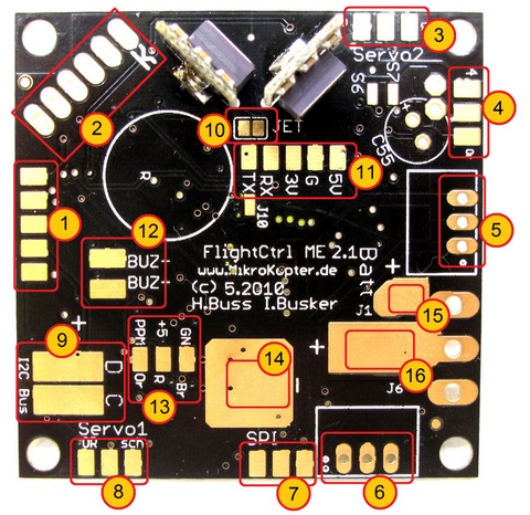
1 - 10pin connector for MK-USB or NaviCtrl connection
2 - Pressure Sensor (cut out of sensor connector points to the right)
3 - 6pin connector for servo 2 and Servo 3
4 - 6pin connector for servo 4 and servo 5
5 - DC/DC voltage regulator 5v Recom for Flight Controller
6 - DC/DC voltage regulator 5v Recom for servos
7 - 6pin connector for NaviCtrl
8 - 6pin connector for servo 1 and switchable J16/J17 connectors
9 - I2C connector (C/D) for BL Controllers
10 - JET (If you are using the Jeti Satellite receiver you will have to bridge these two connectors)
11 - 5pin connector (5V, GND, 3,3V, RX,TX)
Connection for Jeti receiver:
Connect PPM cable to #13, bridge the 2 connectors on #10 and connect RX
Connection for Spektrum Satellite::
Connect the orange Receiver cable on 3,3V, black to G and gray to RX
12 - connection for the buzzer (BUZ-/BUZ+)
13 - Connection for PPM receiver (GN-brown, +5V-red, PPM-orange)
14 - Ground (GND) connection for the Flight Controller
15 - Positive (+) connection for the Flight Controller (if a power switch is being used)
16 - Positive (+) connection for the Flight Controller (without a power switch)
Flight Ctrl. 2.1
The FlightCtrl is already fitted with all needed components.


 The FCV2.1 can be connected to the powerboard via the molex cable.
When using the Molexkabel between FlightCtrl and powerboard, you don't have to solder the I2C bus, the buzzer and the power cable to the FlightCtrl.
Only the power cable for the receiver still has to be soldered to the FlightCtrl.
The buzzer is connected directly to the appropriate solder points of the powerboard (Buzzer / -).
The I2C-bus and the voltage supply are provided from the power distribution via the Molex.
Alternatively, the FC V2.1 can be connected with individual cable to the power distributor. But then you don't have to use the Molexcable.
 When mounting the FlightCtrl, the printed arrow shows to the rigger No.1 (red rigger). The PCB populated side facing up.
Connections

(FC2.1 and FC2.0 are identical except the new Molex Connector)
Connectors SV2
Upper Row (switchable outputs)
Pin1: 100mA switchable output with NON Open Collector for LED's, Programmable with MK Koptertool with J16.
Pin3: +5 Volt
Pin5: 100mA switchable output with NON Open Collector for LED's, Programmable with MK Koptertool with J17.
Lower row: Nick-Servo Output
Pin2: Servo 1 output (for Nick-Servo camera stabilization)(adjustable via MK Koptertool)
Pin4: +5V
Pin6: GND
Attention: the servo outputs get activated after the calibration of the gyros. Push the throttle lever in the upper left corner until you hear the buzzer and the green LED turns off.
Connectors SV3
Upper row: Servo 3
Pin1: Servo 3 output
Pin3: +5V
Pin5: GND
Lower Row: Roll-Servo Output
Pin2: Servo 2 Output (Setting in Koptertool)
Pin4: +5V
Pin6: GND
Connectors SV4
Upper row: Servo 5
Pin1: Servo 5 output
Pin3: +5V
Pin5: GND
Lower Row: Servo 4
Pin2: Servo 4 output
Pin4: +5V
Pin6: GND
Receiver Connection
Standard PPM-Receiver
Examples:
Connection:
- black to "GN" (negative)
- orange to "+5V" (positive)
- orange to "PPM" (data connection)


Spektrum Satellite Receiver
The 3,3V power connection for the satellite receiver is on the bottom side of the Flight Controller.
Connection:
- black to "g" (negative)
- orange to "3,3V" (positive)
- gray to "Rx" (data connection)
- do not bridge the 2 JET connectors.


Also see: Spektrum
Jeti Satellite Receiver
The external diode is already integrated into the FC2.1 circuit and therefore will not have to get soldered.
Connection:
- black to "GN" (negative)
- orange to "+5V" (positive)
- orange to "PPM" (data connection)
- bridge the 2 connectors for JET
- separate data connection for down-link data gets connected via "RX" to "D" or the receiver


Also see: JetiDuplex
Wiring Diagram
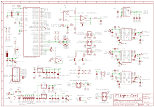
The usage of MikroKopter Software is only permitted on original MikroKopter hardware.
Hardware Changes since V2.00
- new controller with double the flash memory (ATMEGA1284P)
- Molex-connector for easy power distribution board connection
- integrated power supply for Spektrum Satellite receiver
- JET connector bridge for easy usage for JETI down-link
- Adjustable resistor for pressure sensor to accommodate 2000-3000 meters in elevation depending on weather
- resistor adjustment for I2C Pull-Ups.
- Protection diode for Buzzer
- new black color
What's included and what has changed compared with V2.0
- Pressure Sensor MPX4115A is included
- 2 power regulators (recom or similar) are included to supply your flight controller and servos with power
- power switch is NOT includes and has to get ordered separately
Other
- the boot loader for FC2.1 is not public domain and can not be read out thanks to our good friends in china.
a AtMega1284 Prozessor with programmed bootloader is available here
- under no circumstances is it allowed to program or delete the ISP with Atmel programmers