Seite in deutsch |
 This page as a PDF-Document? Simply click the symbol at the right and wait...
See also: BLCtrlAnleitung
Inhaltsverzeichnis

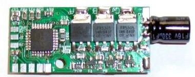
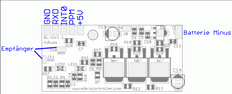
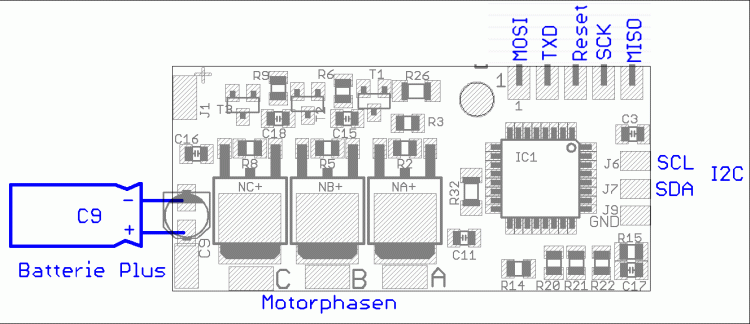
home made controller for Brushless-Motors BL_CTRL_V1.0/V1.1 schematic, component placing and commissioning.
![]() more info for the BL-Ctrl V1.1 can be found here: BL-Ctrl_V1_1
more info for the BL-Ctrl V1.1 can be found here: BL-Ctrl_V1_1
Manual BL-Ctrl
BL-Ctrl
The BL-Ctrl board is a sensorless driver for brushless DC current motors.
They are especially designed for use in QuadroKopters, where quick set-changes are necessary. However, they can also be used for other goals.
Features
- Size 20 * 43mm
Placed with six 60A MosFets
- Continu use ca. 10A (at bad cooling conditions)
- Controller: ATMEGA8 of Atmel
- Current sensing and limiting on the DC side
- Two LEDs (f.e. Okay and Error)
- Battery voltage sensing with low voltage detection
- Software completely written in C (notice Licence agreement!)( beachten)
- Several connectors to enter settings
- The 5V can provide power to a receiver (max. 50mA)
Usable connectors are:
- Asynchron serial connector (for control or debugging)
- I2C (to quickly receive set values)
- PPM-Signal (for a standard input from receiver)

Way of functioning
Die Ansteuerung erfolgt dreiphasig in Impulsgruppen mit überlagerter PWM. The PWM defines the height of the phase voltage (more precise: the arithmatic average of the voltage).
The phase voltage at the motor (also the PWM) is a substitute size for the speed, because a motor produces a reverse voltage by its movement. This voltage works contrary to the provided voltage. A speed is set, at which the difference between set voltage and reverse voltage creates a current according to the lowered torque. There are always 2 MOSFETs in use, to power the coils. The moment of commutation (change to the next phase), is determined by voltage sensing (better: comparision) at the phase which is not in use. To achieve this, the analogue comparator of the Atmega8 is used. The current is determined by voltage-drop over a defined trace.
This procedure is precise enough for blocking overcurrent.
Common assurancy notes
We do not garantee errorless functioning of the controllers. At the moment a voltage is provided to the controller, the motor which is connected to the controller, can start turning or get hot because of errors. Despite careful production and testing, we take no garantee or liability (direct or indirect) for errorless software, hardware or information. Using the controller is for your own responsibility (the same for corresponding pc-programs). Furthermore, we do not take liability for damage to items or persons, which rise by use of the controller. It is your own responsibility to perform a complete system test. The power providence should not be misconnected.
'Wir garantieren nicht für fehlerfreies Verhalten des Reglers. Sobald der Regler mit Spannung versorgt ist, kann der am Regler angeschlossene Motor z.B. durch Fehler o.ä. jederzeit unerwartet anlaufen oder sich erhitzen. Trotz sorgfältiger Erstellung und Überprüfung übernehmen wir keinerlei Garantie oder Haftung (direkter oder indirekter Art) für die Fehlerfreiheit der Software, der Hardware oder von Informationen. Sie benutzen den Regler auf eigene Gefahr (dies gilt auch für dazugehörige PC-Programme). Weiterhin übernehmen wir keinerlei Haftung für Folgeschäden an Sachwerten oder Personen, die durch Anwendung des Reglers entstehen. Es liegt in ihrer Verantwortung, einen vollständigen Systemtest durchzuführen. Die Spannungsversorgung darf nicht verpolt werden.'
Commissioning
Step 1: Connecting and checking the operating voltage
To be sure no unwanted short-circuits are introduced, check the 5V with respect to GND (there are pads with notes "5V" and "GND").
Also, the 12V supply should be checked for short-circuitry (direct at the connections for battery voltage).
At these measures, a resistance clearly above 0 ohm should be noticed. This means, the short-circuit-tester should not beep.
If there is a short-circuit noticed, commonly short-circuits on the 100nF-condensers are the cause. When using solder paste: less is more.
The operating voltage is connected to BAT+ and BAT-. It is highly advised to use a net-supply with current limiting, until you are sure everything is functioning. A socket net-supply with 9-12V DC output voltage will be useful. After connection of the operating voltage, the 5V supply should be tested. Measure the "+5V" connection with respect to ground. This voltage should be between 4,8V and 5,2V.
Step 2: uploading the program
This will be described precisely below.
Step 3: Testing the hardware
When the controller can be programmed succesfully, the motor wires can be soldered. First the I2C wires should be soldered after the complete program is uploaded, because these wires are a part of the programming connector. If more BL-controllers or the Flight-Ctrl are connected to the I2C bus, programming is not possible anymore. The test program „Test_Schub_BrushLess-Ctrl_V0_xx.hex“ has to be uploaded (you can find this in SVN at the HEX-files of hardware version 1.0). If it functions properly, the motor should start smoothly. The following video shows a test running:
After switching on, the leds light shortly. If the motor doesn't start correctly, several reasons can be the cause:
- The MOSFET-bridge (or its driving) does not function correctly.
- The commutation moment is not determined correctly. In this case you should upload the file:
„Test_Manuell_BrushLess-Ctrl_V0_XX.hex“ .
This controls the motor without commutation moment determination. When the motor doesn't spin or not smoothly, usually fault nr 1 is the case. When the motor starts spinning correctly, usually fault nr 2 is the case. The spinning direction of the motor can be reversed by swapping any two motorphases. This is also needed at commisioning of the MikroKopter, because all the controllers create the same AC current. This causes all four motors and so the propellors to rotate in the same direction. In combination with each 2 propellors for right and left runners, the following problem will rise: Two times upwards+ two times downwards = MikroKopter won't fly, at most it starts swinging.
In this case simply check the spinning direction at switching on / off (front / back: clockwise, left / right: counterclockwise) and swap two wires of the coherent motors.
Step 4: Connection of a set-value provider
Now the program „BrushLess-Ctrl_16kHz_V0_XX.hex“ can be uploaded for example. This program uses the PPM connection of the receiver for set value. When using other connections (f.e. serial or I2C bus), it should be tuned to the appropriate set-value provider. There is no standard.
Uploading software into the controller
There are several possibilities to flash the software into the controller. By Sercon and MikroKopter is the easiest way. When this won't work out, alternatively PonyProg can be used for example.
The bootloader should be programmed only once into the AVR. The fusebits will be set automatically by MikroKopterTool.
Next the firmware updates can easily be inserted serial.
IMPORTANT: To flash the bootloader, a real serial connection is needed.
 A bootloader is already installed on the SMD-pre-placed boards.
In case you don't want to use a bootloader, the firmware can be flashed by ISP also. (This is not advisable, though)
Here you can find the bootloader and the BL-ctrl software:
http://mikrokopter.de/mikrosvn/BL-Ctrl/
Flashing the Bootloader
The BL-Ctrl should be connected to the SerCon by a 10-way cable (ISP1), which is a ISP cable and serial cable combined.
- The BL-Ctrl has to be powered.
- No data is allowed from the I2C bus while flashing, so disconnect it or switch off / reset the Flight-Ctrl.
- Choose 'Controller flashen und Terminal'
Place the jumper on the SerCon
- Press 'FLASH' and select the bootloader-hexfile.
- … Now the bootloader will be uploaded - it takes a while -
- after uploading succesfully, the bootloader will reply with a code:
- Vx.y:MKBL
Vx.y = Version
MKBL für MikroKopter-BootLoader
Alternative: Uploading the bootloader with AVR-Studio. The fuses should be set as follows:
Uploading firmware
The BL-Ctrl should be connected to the SerCon again, with the 10-way cable (ISP1), which is a ISP and serial cable combined.
Remove the jumper of the SerCon.
- The BL-Ctrl must be powered.
- The I2C bus connection should be disconnected, when the update is uploaded by ISP.
- Click 'Update' and select the actual hex-file of the BL-Ctrl.
- Now uploading is started. - A manual reset may be required (simply switch off and on the BL-Ctrl).
- When everything went allright, the BL-Controller will answer with its actual version.
- BL-Ctrl V1.0: Each motor controller needs its own address (different hex-files)
- BL-Ctrl V1.1: Each motor controller needs its own address which are set by a shorting
Lötjumper on the board (same hex-files).
- adresses of the motors: 1=Front 2=Back 3=Right 4=Left
Uploading the bootloader with PonyProg
![]() If MikroKopter-Tool (avrdude) causes trouble, PonyProg can be used alternatively to upload the bootloader.
If MikroKopter-Tool (avrdude) causes trouble, PonyProg can be used alternatively to upload the bootloader.
Componentlist and component placing
![]() Tip: It is advisable to scan both sides of the empty board or take a picture of them. This makes life easier when searching for errors or short-circuits.
Tip: It is advisable to scan both sides of the empty board or take a picture of them. This makes life easier when searching for errors or short-circuits.
To place components the easiest way, follow the order in which the components are placed in the next list:
Cursive written components are to be placed at the bottom side
Anz |
Reichelt-Best.Nr. |
Suggestion |
Component |
Name |
1 |
ATMEGA8-16TQ |
Watch marking, use flux! |
Controller |
IC1 |
3 |
BC817-16SMD |
|
Transistor |
T1, T2, T3 (Version 1.0 and 1.1) |
3 |
PDTC143ET |
The basic front resistors R3, R6 and R9 should be replaced by a low-resistance resistor f.e. 100 Ohm |
Transistor |
T1, T2, T3 (Version 1.2) |
1 |
4k7 SMD 1/4W |
|
Resistor |
R26 |
1 |
10R SMD 1/4W |
|
Resistor |
R32 |
2 |
4k7 SMD-0805 |
|
Resistor |
R6, R9 |
6 |
X7R-G0805 100nF |
|
Conderser |
C3, C15, C16, C17, C18, C11 |
5 |
4k7 SMD-0805 |
|
Resistor |
R3, R20, R21, R22, R15 |
3 |
470R SMD-0805 or 680R SMD-0805 |
|
Resistor |
R2, R5, R8 |
1 |
18k SMD-0805 |
|
Resistor |
R14 |
1 |
SMD-LED 0805 GR |
Watch placement! |
CHIPLED |
LED1 |
1 |
SMD-LED 0805 RT |
Watch placement! |
CHIPLED |
LED2 |
9 |
X7R-G0805 100nF |
|
Condenser |
C1, C2, C4, C5, C6, C7, C8, C10, C13 (Version 1.0) |
12 |
X7R-G0805 100nF |
|
Condenser |
C1, C2, C4, C5, C6, C7, C8, C10, C13, C14, C19, C20 (Version 1.1) |
7 |
4k7 SMD-0805 |
|
Resistor |
R1, R4, R7, R11, R12, R13, R18 |
2 |
1k SMD-0805 |
|
Resistor |
R27, R33 |
4 |
18k SMD-0805 |
|
Resistor |
R10, R16, R23, R24 |
3 |
100R SMD-0805 |
|
Resistor |
R17, R19, R25 |
3 |
IRFR1205 |
alternativ also IPD03N03LB, IRLR7843 |
MOSFET |
NA-, NB-, NC- |
3 |
IRFR5305 |
alternativ also FDD6637 |
MOSFET |
NA+, NB+, NC+ |
2 |
SMD Elko 10/16 |
Watch marking |
Elco |
C12, C14 (Version 1.0) |
1 |
SMD Elco 10/16 |
Watch mark |
Elco |
C12 (Version 1.1) |
1 |
RAD330/16 |
watch polarisation and solder from aside |
Elco |
C9 |
1 |
TA78L05 or µA78L05 |
|
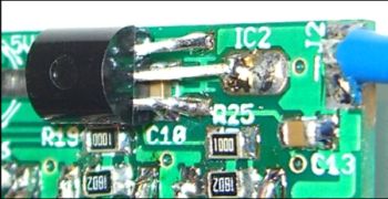
voltage controller |
IC2 (Conrad: 144711 - 62) |
Other stuff
- 1 connector EC10 - programming connector
- 1 D-SUB ST 25 - Sub-D connector for parallelport-programming cable
- 0,5m 10-way flatcable
- 1m connection wire
tools
- CR44 tin containing SMD flux
- Desolderinglitze AA desolderinglitze 1,5mm
- Soldering tin AG 0,507 soldering tin 0,5mm
- Wired voltage controller, in case not available in SMD

Alternative MosFets for better achievements
With better MosFets, continously 10A and peak 20A current is possible. Following changes have to be made:
IRFR1205 (NA-, NB-, NC-) exchanged by: IRLR7843 or IPD03N03LB (Infineon)
IRFR5305 (NA+, NB+, NC+) exchanged by: FDD6637 or SPD50P03L (Infineon)
Both Infineon MosFets have the best characteristics, at the SPD50P03L the wires should be bent a little.
After exchanging, the 10A-firmware should be uploaded to the controller. They will function with the 6A-firmware, but then motor achievements are wasted.
- The actual software can be found in SVN:
Link Beside the Infineon MosFets, better Fets can be order at MK-Shop. These will be present on the bestuckte controller boards.
Connecting


Schematic

(Click for higher resolution)
IMPORTANT
![]() The Controllers have to be protected against moist. (Destroyment of the Fets!)
The Controllers have to be protected against moist. (Destroyment of the Fets!)
- So absolutely use shrink tubing or isolation spray (plastic spray) to protect the controllers!
To achieve a better resistance against moist, PDTC143ET transistors of NXP can be used on controller version 1.2. These are included in the MosFets set at H&I Shop.

