Inhaltsverzeichnis
- Step 1 - Kopter-Check
- Step 2 - Prepare PC
- Step 3 - Connect the Kopter with the PC
- Step 4 - Switch ON the Kopter
- Step 5 - First check in the !KopterTool
- Step 6 - Open the settings
- Step 7 - !EasySetup - Basic settings
- Step 8 - Set receiver and transmitter
- Step 9 - Check channels
- Step 10 - Camera mount
- Step 11 - Outputs
- Step 12 - Calibration
- Step 13 - Motor, Propeller and Gyro Check
- Step 14 - Control commands
Step 1 - Kopter-Check
Before the Kopter will be powered up the first time after a successful assembly you should review your work again.
![]() For that reason that it is an electronic model a solder bridge or an improperly connected cable can destroy hours of work within seconds.
For that reason that it is an electronic model a solder bridge or an improperly connected cable can destroy hours of work within seconds.
What should you check?
Here are some hints:
The red outrigger is pointing forward/to the front?
The FlightCtrl is mounted correctly (with the SMD parts upwards)?
The FlightCtrl is pointing with the arrow forwards to the red outrigger?
The propellers were properly aligned and mounted with the correct direction?
All bolted connections were made correctly?
Visual check of all solder joints.
Visual check of all connected cables.
The power distribution board has been checked for shorts? (Check help)
If you have allready mount the GPS-System, is it correct connected? (Check help)
Also this should be checked:
At the transmitter a model memory with a fixed-wing model (ACRO) has been set up.
The transmitter has been set to your desired MODE (MODE 2 is the regular mode).
The channels on the transmitter are assiged to switches, buttons and potis.
The receiver was bound with the transmitter?
The receiver gives a PPM sum-signal?
(or has it been changed to - i.e. necessary at the receiver of the HoTT transmitter => Link)?
The receiver is connected to the FlightCtrl ? (Check help)
Step 2 - Prepare PC
Requirement
Step1 has been read.
Prepare the PC
To check and to adjust the Kopter right after the power-up the KopterTool has to be installed on your PC/Laptop.
To make all your settings with the KopterTool to your Kopter you need to have a connection between the Kopter and your PC/Laptop. This requires the MK-USB.
1. MK-USB
First at all you need to solder the both 10-pole pin-header and the 2-pole pin-header for the jumper to the MK-USB board:
(Please make sure you solder properly!)
After that the required Windows-driver can be downloaded here: VCP-Treiber
(Who is using a Linux-PC or a MAC can also download here the appropriate drivers)
If the MK-USB is connected to the PC/Laptop it can be installed with the driver.
INFO
After the installation you can check in the Windows device manager which COM-Port has been asigned for the MK-USB.
That COM-Port must be entered later on in the KopterTool.
Into the device manager you can switch also over the control-panel or you enter under >Start >Execute "devmgmt.msc".
(More information about the MK-USB you can read here: MK-USB)
2. KopterTool
Is the MK-USB now installed and connected to your PC/Laptop you can download the KopterTool.
The actual version you can get here: MikroKopter-Tool
TIPP
If you are not able to download the file with a "Left-click" of your mouse you should open the context menu with a "Right-click"
and there click on "SAVE Target as...".
 The KopterTool is a Windows-based program.
If you want to use this program on a Linux computer or a MAC you need to have Windows-compatible runtime enviroment
like i.e. Wine, Darwine or WineBottler. (Detailed describtion you can get from the appropriate program.)
The downloaded file is packed in a ZIP-file and need to be unzipped. This you can do i.e. with a packing-program like 7-zip or WinRAR.
After unpacking the file you have a folder named Kopter_Tool_Vx_xxx (the "x" is asigned for the version-No.!).
In this folder you can find the file MikroKopter-Tool.exe. If you open the file by double-clicking on it you will start the KopterTool.
At the first start you see the license window:
This window displays the license agreement to use the tool MikroKopter. Also you can chose the language and the COM-port.
The COM port should be set to the MK-USB.
(Which COM port is assigned to the MK-USB, you can control in the Windows Device Manager under COM and LPT ports.)
With a "click" on Akzeptieren / Accept you accepted the license conditions, the default language setting and the COM port.
Now you see the start window of the KopterTool:
(View without attached board)
(Further information about the KopterTool you can find here: KopterTool)
Step 3 - Connect the Kopter with the PC
Requirement
Step2 has been read.
Connect Kopter with PC
Is the KopterTool and the MK-USB installed and set up there is now a good time to connect the Kopter over the MK-USB to your PC/Laptop.
Here now you need to connect right in polarity the ribbon cable to the MK-USB and the FlightCtrl (or another module).
![]() If you connect the ribbon cable in a wrong way you may be damage the boards.
If you connect the ribbon cable in a wrong way you may be damage the boards.
Two things you should know:
On ALL boards is on the TOP-side and on the right next to the pin-header a "1" printed.
The ribbon cable has on one side a red mark.
The red mark should point to the printed "1".
Wether or not if you have connected only the FlightCtrl or already the GPS-System, the connection to the Kopter looks in that way:
The jumper on the MK-USB has to be open.
Step 4 - Switch ON the Kopter
Requirement
Step3 has been read.
Supply Kopter with voltage
Tip 1
- The Kopter should stand on a stable and even ground.
- A sticker on the buzzer will reduce the volume of the "beeps". This is sparing your nerves during error messages ;-)
- For the first test you do not need to have the propeller mounted.
(So in that way you can do motortests without a risk of injury.)
Tip 2
You can use for the first startup a stabilized power supply (12V/1,5A).
You can hook up also directly the Lipo.
In case of an error (Shortage, soldering defects etc. ) a power supply with current limitation protects the electronic for bigger damage.
Now turn on first the remote control and after that supply power to the MikroKopter
Example photo: |
Example photo: |
Tones after switching ON
After the Kopter has been supplied with power all BL-Ctrl's are starting their self-test after a short beep out of the buzzer.
All motors are "beeping" and moving one time. There is no specific order in which the BL-Ctrl's are performing their tests.
(INFO: This tests of the BL-Ctrl's with connected motors are been done even if the FlightCtrl is not connected!).
Now you should hear different beep-tones out of the buzzer. First at all comes a short "beep" followed by more and longer "beeps".
Is i.e. a 4S-Lipo connected comes after a short "beep" 4 a little bit longer "beeps".
With a connected 3S Lipo comes after a short "beep" 3 a little bit longer "beeps".
Example:
On a QuadroKopter with connected 4S Lipo the "beeping" should be in that way:
Switch ON |
BL-Ctrl Test |
Confirmation "beep" + battery detection |
beep |
beep (+Motor) - beep (+Motor) - beep (+Motor) - beep (+Motor) |
beep + beeeep-beeeep-beeeep-beeeep |
After those "beep tones" the Kopter should be silent.
HELP
If the Kopter "beeps" continuously in intervals then please read here first: 
(You can disconnect the Kopter from the power supply/Lipo at that time.)
LEDs FlightCtrl
The green LED of the Flight-Ctrl should light now, the red LED is OFF and the buzzer is silent.
![]() Is the red LED on the FlightCtrl OFF and the buzzer beeps continuously in intervals it could be possible
Is the red LED on the FlightCtrl OFF and the buzzer beeps continuously in intervals it could be possible
that the connected Lipo is empty and should be charged again. Infos about the Lipo's and charging them you can find here: LiPo
LEDs BL-Ctrl
On the BL-Ctrl's each green LED is ON and the red LEDs are OFF.
 Exception for HexaKopter and OktoKopter:
At the Kopter only the BL-Ctrl's with the addresses 1-4 should have the green LED on.
On a HexaKopter the BL-Ctrl's with the addresses 5+6 the green and the red LED should be permanently ON.
On an OktoKopter, the BL-Ctrl's with the addresses 5+6+7+8, the green and the red LED should be permanently ON.
That is normal. The right mixer is not set in the KopterTool.
If the right mixer is set the green LED of the remaining BL-Ctrl's are ON.
 How to set up the mixer in the right way is described on the next and following "Step"-Sides.
HELP
If on a BL-Ctrl the red LED is blinking or there is no LED ON an error occured. Assistance on how to proceed can be found here: 
LEDs NaviCtrl / GPS
If a GPS-System is already mounted the LEDs are lighting as follows:
NaviCtrl V2.0 => green and red LED ON.
- (The red LED goes off after calibrating the compass. This will be described on the following "Step"- Sides.)
NaviCtrl V1.1 + MK3Mag => green and red LED ON. LED on MK3Mag is blinking.
- (The red LED goes off after calibrating the compass. This will be described on the following "Step"- Sides.)
MKGPS V1.0 => LED on the TOP-side lights permanently. After a Satfix this one is blinking.
MKGPS V2.1 => LED on the BOTTOM-side lights permanently. LED on the TOP-side lights permanently + flashes after a Satfix.
Step 5 - First check in the !KopterTool
Requirements
Step4 has been read.
First check in the KopterTool
Depending on which Kopter is connected (Quadro, Hexa or Okto) the displays of the KopterTool are different in the virtual display.
Below of the virtual display is also a status indicator. Here you can determine quickly if everything is OK (green status indicator) or if there is an error (red status indicator).
Is a status indicator red another button appears next to it "Details..." . One "click" on the button tells you more about the possible error.
It should be your target to have all indicators on green.
The displays for a QuadroKopter should be in that way as shown in the examples under: View QuadroKopter.
If you have a HexaKopter or OktoKopter connected it should be in that way as shown in the examples under: View of HexaKopter or OktoKopter.
View QuadroKopter
The FlightCtrl has as a standard mixer the "Quadro" set up. If you have now a QuadroKopter connected the display in the KopterTool should be in that way:
Example View KopterTool V1.76b: |
Example View KopterTool V1.76b: |
Example View KopterTool V1.76b: |
Only FlightCtrl mounted on the Kopter |
FlightCtrl and NaviCtrl V2.0 mounted |
FlightCtrl, NaviCtrl V1.1, MK3Mag mounted |
This display shows: *All OK* |
This display shows: *Almost all OK* |
This display shows: *Almost all OK* |
Only FlightCtrl on the QuadroKopter:
All Status displays are on green = ALL is OK.
FlightCtrl + GPS-System on the QuadroKopter:
Red Status display shows us that something is not OK.
Here now and depending on the used NaviCtrl a bad compass value or a Magnet error will be displayed.
Getting the information Magnet error you should click on the button Details....
If here is as an error a missing compass calibration indicated you must, as well as with a bad compass value, calibrate the compass.
Just only calibrate the compass, an error is not indicated.
Before the compass is calibrated, however, a few other settings are required.
How that works is written in a different Step further down the road.
![]() With each new NaviCtrl V2.0 (or MK3Mag) the compass is still not calibrated. For that reason an error message with a red status display is shown.
With each new NaviCtrl V2.0 (or MK3Mag) the compass is still not calibrated. For that reason an error message with a red status display is shown.
View HexaKopter or OktoKopter
If a HexaKopter or OktoKopter is connected the actual set up standard mixer "Quadro" shows you the first 4 BL-Ctrl's but not the other ones.
The display in the KopterTool looks in that way:
Example View KopterTool V1.76b: |
Example View KopterTool V1.76b: |
Example View KopterTool V1.76b: |
Only FlightCtrl mounted on the Kopter |
FlightCtrl and NaviCtrl V2.0 mounted |
FlightCtrl, NaviCtrl V1.1, MK3Mag mounted |
This display shows: *Almost all OK* |
This display shows: *Almost all OK* |
This display shows: *Almost all OK* |
Only FlightCtrl on the Hexa- or OktoKopter:
For that reason that the default "Quadro"-Mixer just only displays the first 4 BL-Ctrl and not the remaining BL-Ctrl's of the Hexa- or OktoKopter,
a Mixer Error is shown. If the right mixer for the Hexa or Okto is choosen everything is OK again.
FlightCtrl + GPS-System on the Hexa- or OktoKopter:
Also here shows the default "Quadro"-Mixer just only the first 4 BL-Ctrl's and not the remaining BL-Ctrl's of the Hexa- or OktoKopter.
If the right mixer for the Hexa or Okto is choosen everything is OK again.
How that will be done is described in a later Step.
![]() With each new NaviCtrl V2.0 (or MK3Mag) the compass is still not calibrated. An error message in form of a red status indicator is displayed.
With each new NaviCtrl V2.0 (or MK3Mag) the compass is still not calibrated. An error message in form of a red status indicator is displayed.
After the right set up of the mixer the nissing compass calibration will be shown.
How that will be done is described in a later Step.
Step 6 - Open the settings
Requirement
Step5 has been read.
Open the settings
To set up the Kopter (in example the mixer) and to check on the functions of the transmitter you need to switch in the KopterTool to the .
After a click on the button "Settings..." the following window should appear:
INFO
If after a "click" on this window appears....
... is the software version on the FlightCtrl/NaviCtrl NOT compatible with the used KopterTool.
In that case the software of the FlightCtrl and the NaviCtrl should be updated.
Step 7 - !EasySetup - Basic settings
Requirement
Step6 has been read.
Basic settings
Here in the EasySetup the first basic settings will be made.
Height regulator
Height regulator
With this function you can keep automatically the height of the Kopter during a flight.
![]() Switch ON the function
Switch ON the function
The height regulator on the FlightCtrl2.1 is installed by default. Here now the function should be activated. ("click" into the box)
As a switch channel (nominal value) is already Poti 1 => Channel 5 set by default.
Is a switch on the transmitter assigned to the channel 5 you can switch ON/OFF this function direct from the transmitter.- Function/Switch ON: The Kopter is holding in ~middle position of the throttle stick automatically the height.
- Function/Switch OFF: The Kopter need to be hold manually in the height.
As a Stick Neutral Point "0" is set by default. This value usually will be NOT changed.
Here you must set only a different value if you use a throttle stick with a centered spring (The throttle stick stays automatically in the middle position).
(The function is described here: Link)
GPS
The functions of the GPS can be used only, if the GPS-System (NaviCtrl with compass + MKGPS) is mounted to the Kopter and also connected.
![]() Switch ON the function
Switch ON the function
If the GPS will be activated you can use additional functions.
For the GPS Control Mode is already the Poti 2 => Channel 6 set by default.
Is a 3-way switch on the transmitter assigned to this channel 6 you can switch from the transmitter to the functions PositionHold and ComingHome. (Further information you can find here: Link)
In addition you can activate also the Dynamic PositionHold and set up the function ComingHome Altitude.
(More information you can find here: Link)
CareFree
With the GPS-System you can use also the function CareFree. This function can help the newcomer to learn how to fly way easier.
![]() Assign a free channel to this function
Assign a free channel to this function
This function can be also placed like the GPS or the height regulator to a switch on the transmitter (Poti1-8).
Is this function switched OFF, the red outrigger is pointing to the front.
Is this function switched ON, it doesn't matter in which direction the red outrigger points.
The function Teachable CareFree makes it easier to use the CareFree and provides more functions.
(An explaination of this function you can find here: Link)
Motor-Safety Switch
To prevent that the Kopter will be switched off accidentally during a flight a motor safety switch can be set.
![]() Assign a free channel to this function
Assign a free channel to this function
This function can be assigned with a free channel and then over a switch on the transmitter to enable/disable those functions.
INFO: The Kopter will be with "Throttle down + Yaw left" switched OFF. So that you do not turn OFF the Kopter accidentally during a flight this function can be enabled/disabled.
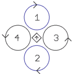
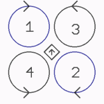
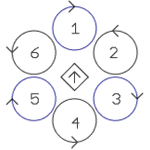
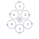
Set the mixer
Is a QuadroKopter connected (4 Motors) it is not necessary to change something.
Was a HexaKopter (6 Motors) or an OktoKopter (8 Motors) connected the error Mixer Error has been shown in the virtual display.
To eliminate this "Error" you must set the right mixer:
One "click" on the button "Load..." opens a selection of existing mixers.
It depends on which Kopter you have you need to choose the appropriate mixer. The mixer you can find here:
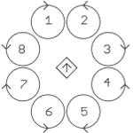
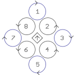
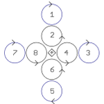
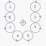
INFO: .mkm Dateien => (the direction of rotation per motor will be shown in a graphic)
Quadro.mkm |
Quadro-X.mkm |
Hexa.mkm |
Hexa2.mkm |
|
|
|
|
For Basisset: |
For Basisset: |
For Basisset: |
No Basisset |
Okto.mkm |
Okto2.mkm |
Okto3.mkm |
Okto-U |
|
|
|
|
For Basisset: |
For Basisset: |
No Basisset |
No Basisset |
![]() The arrow in the middle represents the flight direction (forward) .
The arrow in the middle represents the flight direction (forward) .
If the right mixer has been chosen with "OPEN" the selection window will close. On the right of the Mixer-SETUP you can see the name of the mixer.
Those settings must be written now into the FlightCtrl.
Here a "click" on the button WRITE is enough.
Step 8 - Set receiver and transmitter
Requirements
Step7 has been read.
Set receiver
After you have set the basic settings the function of the receiver and transmitter should be checked/set.
Here we need to open the second tab: Channels
To make sure that the ways of the sticks and the switches/buttons/potentiometer from the transmitter are implemented properly in the KopterTool and also on the Kopter. You must set first the appropriate receiver:
Note for Jeti transmitter: MikroKopter messages will be transferred essentially via morse code message. In the latest Jeti-transmitter (i.e. DC-16 etc.) an own language sequence can be assigned to the messages.
For that reason that also the switch messages like “Altitude ON” are transferred, those can be deactivated with Telemetry: Speak all events in the KopterTool (older transmitter would give in this case a morse code and beep).
There are available:
Multisignal (PPM) Standard receiver (e.g. ACT DSL4 top, 2.4GHz-Receiver R6107SP)
(Connection at the PPM-Input of the FlightCtrl)Spektrum Satellit
2.4GHz satellite receiver Spektrum
(connect to the 2nd serial port of the FlightCtrl)
Spektrum Satellit (HIRES)
2.4GHz satellite receiver with high resolution of Spektrum (2048) (e.g. DSX7, DX8, DSX9, DSX12)
(connect to the 2nd serial port of the FlightCtrl)
Spektrum Satellit (LowRES)
2.4GHz satellite-receiver with low resolution (512) (is used in some plug-in modules)
(connect to the 2nd serial port of the FlightCtrl)
Jeti Satellit
2.4GHz Jeti Satellit (e.g. RMK2)
With this setting, the output of the telemetry is activated too.
Displayed is the telemetry on the Jeti Box.
(Connection at the PPM-Input of the FlightCtrl + connection to the 2nd serial port for telemetrie)
ACT DSL
Connecting a ACT DSL-signal on the 2nd serial port on the FlightCtrl
Graupner HoTT
2.4GHz Graupner HoTT Empfänger (e.g. GR-12, GR-16, GR-24)
With this setting, the output of the telemetry is activated too.
Displayed is the telemetry on the display of the transmitter.
(Connection at the PPM-Input of the FlightCtrl + connection to the 2nd serial port for telemetrie)
Futaba S.BUS
2.4GHz Futaba S.BUS Receiver
To connect a S.BUS Receiver to th eFlightCtrl you need a Signal inverter (Shoplink).
(connect to the 2nd serial port of the FlightCtrl)
User
- Free for programmer
(How to connect a receiver you can see here: Receiver)
See INFO
![]() If the appropriate receiver was choosen you need to save the changes into the FlightCtrl: This will be done with a "click" on the button WRITE.
If the appropriate receiver was choosen you need to save the changes into the FlightCtrl: This will be done with a "click" on the button WRITE.
INFO: The HoTT-Telemetry is supported from the FlightControl V2.1 with the current software.
More informations about the HoTT system you can find here: HoTT-transmitter
Set transmitter
To fly horizontal with the copter, you have to check the stick settings on your transmitter.
If both joysticks are in the center position, the trim of this channels 1-4 have to be in the middle in the KopterTool.
If necessary you have to set the trim on the transmitter.
![]() If the trim is perfect a changing during flight is not needed.
If the trim is perfect a changing during flight is not needed.
Step 9 - Check channels
Requirement
Step 8 has been read.
Check channels
Under the tab Channels will be displayed on the left side the individual channels and also their allocation:
The channels 1 - 4 are assigned for the control of Throttle, Yaw, Nick and Roll.
The channels 5 - 12 are assigned to the POTI's 1 - 8.
Those POTI 1 - 8 can be assigned to each function in the setting.
On the right side you can find a graphical display of the channels. Below the display there is the channel, above the set value.
Has been the receiver correctly set up and saved the display should look in that way:
Example View 1: |
Are the channels on the transmitter already correctly assigned the display may look like this:
Example View 2: |
If you move the control stick or press a switch on the transmitter the appropriate channel (bar) should change.
We assume in the Example View 2 that the transmitter is set up in MODE 2. For a transmitter which is set in a different mode the display is pretty similar.
In the Example View 2 we will see as follows:
Channel 1 (Throttle) => Stick down
Channel 2 (Roll) => Stick in middle position
Channel 3 (Nick) => Stick in middle position
Channel 4 (Yaw) => Stick in middle position
Channel 5 (POTI1) => "ON" (i.e. Function !Hold Height => 2-way switch at the transmitter)
Channel 6 (POTI2) => "OFF" (i.e. Function GPS "Free-PH-CH" => 3-way switch at the transmitter)
Channel 7 (POTI3) => "OFF"(i.e. Poti at the transmitter on "left stop")
Channel 8 (POTI4) => "OFF" (i.e. Function CareFree => 2-way switchat the transmitter)
Channel 9 (POTI5) => "OFF"(i.e. 3-way switch at the transmitter for further functions)
Channel 10 (POTI6) => "OFF"(i.e. 2-way switch at the transmitter for further functions)
Channel 11 (POTI7) => a little bit over middle position (i.e. Poti at the transmitter "turned not quite centered")
Channel 12 (POTI8) => "OFF" (i.e. button at the transmitter to trigger a camera)
![]() Moving the sticks or using the switches/buttons/potis the values above the graphical display should be in that way:
Moving the sticks or using the switches/buttons/potis the values above the graphical display should be in that way:
Servo travel |
||||||
Stick for |
Stick for |
2- or 3-way |
Button at the |
Poti at the |
Display/Value |
|
Stick |
Stick |
Switch |
Button |
Poti |
Value = 0 |
|
Stick |
Stick |
Switch |
Button |
Poti |
Value = 254 |
|
Stick |
Stick |
3-way Switch on |
- |
Poti on |
Value = 127 |
|
![]() Is the display looking like as shown here you must set up correctly the "Servo settings" at the transmitter:
Is the display looking like as shown here you must set up correctly the "Servo settings" at the transmitter:
Here we can see that the value of the Servo at the transmitter is not in the range from "0" to "254" but only from "3" to "252".
With these wrong servo values a malfunction can occur. To avoid that should be on the transmitter for each channel the servo travel been adjusted properly.
The exact procedure and the setting are described in the instructions of the transmitter.
TIPP:
At the transmitter the menu point is called mostly "Servo Settings".
The servo travel can be changed for each channel at the transmitter. As a basic setting for each channel is 100%/100% set.
Why 100%/100% ?
For each channel whether it's a joystick, switch, button or potentiometer on the transmitter, it rules the servo travel. This is from -125 <=> 0 <=> +125.
The first 100% are assigned for the lower Servo travel (from -125 to 0) and the second 100% for the upper Servo travel (from 0 to +125).
To make it a little bit easier the servo travel is shown in the KopterTool from 0 <=> 127 <=> 254.
Now you can select the values 100%/100% and increase it slowly. The number should change over the appropriate channel in the display of the KopterTool.
Both percentage values should be increased with the same value. Is now the lower Servo travel i.e. raised to 105% should the upper Servo travel also been raised to 105%.
Step 10 - Camera mount
Requirement
Step9 has been read.
![]() Who has got no camera mount right now at the Kopter can skip this point and continue with the next "Step".
Who has got no camera mount right now at the Kopter can skip this point and continue with the next "Step".
Install Camera mount
If already a camera mount is assembled to the Kopter it need to be connected correctly to the FlightCtrl:
Set Camera mount
Is a camera mount assembled to the Kopter can these be controlled via the FlightCtrl and automatically kept in balance.
Under the tab Camera the function can be set for that.
After the calibration of the Gyros (is described in a later "Step") the camera mount is adjusting by itself.
Previously the servos are not activated and have no reaction to commands / movements of the Kopter.
The "Servo control" has a pre-set value of 128 for the orientation of the camera mount:
Is the camera mount after the calibration not straight you can change the values for Nick and Roll to compensate this.
You can increase/decrease the value. After saving the new value by clicking the button WRITE the camera mount changes accordingly.
You can repeat this as long as the camera mount is straight under the Kopter.
If you want to adjust yourself the tilt over a potentiometer at your transmitter in addition to the automatic alignment of the camera mount,
you can enter a fixed value with the "Servo control" instead of a potentiometer. We remember: the POTI 1-8 are assigned to a channel.
In our example in the previous "Step 9" there is a potentiometer at the transmitter assigned to Channel 7. This is in the channel setup's POTI 3.
This POTI 3 => Channel 7 we can enter for Nick instead of the fixed value:
With this settings you can change now the tilt (Nick direction) of the camera mount over the potentiometer at your transmitter.
If you want to set yourself also the Roll direction over a Poti at your transmitter, you need to assign a free channel. That channel need to be entered under Roll and over the appropriate POTI 1-8.
![]() The alignment of the camera mount will be done over the Poti's at your transmitter.
The alignment of the camera mount will be done over the Poti's at your transmitter.
The Nick compensation needn't be changed. This setting controls the influence of the nick angle and the roll angle in correspondence to the servo.
The servo travel for both servos is already set by default under Servo min: and Servo max:.
Who still needs a greater servo travel can adjust this here:
There are no needs to set up more right now. More information about different settings you can get later here: MK-Parameter
Step 11 - Outputs
Requirement
Step10 has been read.
![]() Who has got no ShutterCable assembled to trigger the camera or an ExtensionPCB to switch the lighting on the Kopter can skip this point and continue with the next "Step".
Who has got no ShutterCable assembled to trigger the camera or an ExtensionPCB to switch the lighting on the Kopter can skip this point and continue with the next "Step".
ExtensionPCB oder ShutterCable
If already an ExtensionPCB to control the lighting or a ShutterCable to trigger the camera has been mounted to the Kopter
the connection should be look in that way:
ShutterCable at output 1 or 2 |
||
Setting Outputs
The FlightCtrl has got two switch outputs. These outputs can be independently switched and set.
You can let flash the LEDs or you can switch them ON/OFF. Also you can use an output to trigger a camera.
The both switching outputs you can find on the upper pin header SV2 on the FlightCtrl:
A ground potential will be switched here!
ATTENTION
The lighting should be NOT directly connected to that outputs. The transistors on the FlightCtrl could be damaged!
To switch the lighting you should use i.e. the Extension-PCB. Over that PCB you can connect the lighting (also with nmore power).
To trigger the camera you can use the Extension-PCB as well as the ShutterCable.
To set up a blink sequence on an output you can choose throughout the 8 boxes in the Bit mask different flash pattern.
The speed of the blink sequence you can set with a number under Timing:
Example Output1 (OUT1)
If you want to trigger a camera over an output (i.e.with a ShutterCable) you can set it here also.
You should only activate the first box in the Bit mask. Under Timing the channel (POTI) of the button will be set here at the transmitter:
Example Output1 (OUT1) Poti 8 => Channel 12
If an output was set to trigger a camera you should disable the Low voltage warning for that output.
Otherwise with an empty Lipo and the following battery warning the camera would trigger continuously:
Example Output1 (OUT1) = OFF
As soon as you save this settings with the button into the FlightCtrl the LEDs strat to flash or you can trigger a camera.
(With a connected LED-Lighting the LEDs start blinking with a low voltage warning.)
INFO
You can use also a switch/channel at your transmitter to switch the LEDs.
Independently of the set flashing pattern you permanently switch the LEDs with the switch ON or OFF.
If you can not
-switch OFF the lighting with a switch/button on your transmitter
- or
- not triggering the ShutterCable
it is the fact that the servo travel is not set up right at the transmitter! That was explained in the previous step "Check channels".
After these settings you can close the setting window. Here you need to "click" on
We are now back to the "Main Window" of the KopterTool.
Step 12 - Calibration
Requirement
Step11 has been read.
Calibration
Now that in the previous "Step's" the right function of the transmitter has been checked and (if necessary) the right mixer has been set,
you can start with the calibration.
Calibration ACC
First at all you calibrate the ACC. That you have to do only one time.
(Only in case of an error or after downloading new software you should repeat it)
1. The Kopter should stand straight.
(An inclined position influence the calibration and leads to errors during the start or in the flight behavior.)
A circular level can help to align the Kopter in a straight way: Link
2. Over the transmitter the ACC will be now calibrated.
Here now you need to move |
On a transmitter in MODE 2 |
Throttle up + Yaw right |
3. The Kopter acknowledges the ACC calibration with beep-tones.
Depending on where in the 5 Setting's you are the Kopter confirms with that numbers of beeps.
Example: We are in the Setting 3 (Easy). The Kopter "beeps" 3x to confirm.
DONE
Calibration Gyro's
Before every initial startup or after changing the Lipo a new calibration of the Gyro's must be done.
If you don't do it the Kopter will give you an error message and "beebs" while trying to start the engines.
INFO: The servo outputs of the FlightCtrl are only available over the transmitter (if set) after the calibration of the gyros. Not before.
1. The Kopter should stand on the ground and not moving or shaking (IMPORTAND !!!).
(The Kopter can stand horizontal or also be stand hillsided in an inclined position. For a horizontal flight of the Kopter the right calibrated ACC will help!)
2. Over the transmitter now calibrate the Gyro's.
Here now you need to move |
On a transmitter in MODE 2 |
Throttle up + Yaw left |
3. The Kopter acknowledges the ACC calibration with beep-tones.
Depending on where in the 5 Setting's you are the Kopter confirms with that numbers of beeps.
Example: We are in the Setting 3 (Easy). The Kopter "beeps" 3x to confirm.
DONE
Calibration Compass
Is on a Kopter already the GPS-System installed (NaviCtrl, Compass, MKGPS) you must calibrate the compass.
Until this is done, in the virtual display you see the "error6" message.
(If you doesn't calibrate the compass, you can not start the Kopter and he will "beep" if you try to start him.)
It depends on a right calibrated compass that the function of the GPS-functions like PositionHold" works well.
1. Disconnect the Kopter from the MK-USB.
If you want to calibrate the compass correctly you should go outside.
 Subjected to any disturbing magnetic influences you shouldn't do the calibration close to the house or close to power poles.
2. Over the transmitter the compass will be now calibrated.
The LEDs look in that way:
NaviCtrl V2.0 =>
green and red LED ON.
NaviCtrl V1.1 with MK3Mag=>
NaviCtrl V1.1 = green and red LED ON, MK3Mag = green LED flashes.
The calibration will be done in several steps:
Step |
Function |
Example View / Function |
Step 1 |
Nick down |
On a transmitter in MODE 2 it lokks like in that way: |
Step 2 |
Pull Nick down 1x |
|
Calibration of the X-Axis (Nick-Axis) |
The Kopter with the front |
|
Calibration of the Y-Axis (Roll-Axis) |
Rotate the Kopter by 90° |
|
Step 3 |
Pull Nick 1x down |
|
Step 4 |
Pull Nick 1x down |
|
Calibration of the Z-Axis (Yaw-Axis) |
INFO: Here it doesn't matter if the Kopter shows with the X or Y-Axis towards South (North). |
|
Step 5 |
Pull Nick 1x down |
3. Now that the Kopter "beeped" 2x after a successful calibration that part is done.
If everything is OK the red LED stops lighting after a few seconds on the NaviCtrl V2.0 with integrated compass.
If you use a NaviCtrl V1.1 with MK3Mag the red LED on the MK3Mag lights permanently.
DONE!
After the calibration of the compass the Kopter can be connected again to the MK-USB.
Check in between
After those settings:
- Set the right mixer (if necessary)
- Calibration ACC
- Calibration Gyros
- Calibration Compass (if GPS-System has been assembled)
... all buttons should be green in the KopterTool:
Only FlightCtrl at the Kopter |
FlightCtrl with GPS-System at the Kopter |
Step 13 - Motor, Propeller and Gyro Check
Requirement
Step12 has been read.
Last Check
Now the function of the FlightCtrl and of the engines should be checked.
If not already done you can remove the propellers now for the motor-test.
In that way you can check safely the direction of the rotation and also the function of the engines and without that the Kopter lifts off.
Motortest
Here now you need to open under the virtual display the tab "Motortest".
The procedure is as follows:
"Motortest active" has to be activated.
"Address" = Choose motor you want to test.
Slider push slowly with the mouse upwards.
That can be done now for each motor.
Tipp:
If a motor is turning the wrong way it is actually enough to switch two of the three motor cables on the appropriate BL-Ctrl.
Propeller assembly
On the Kopter left and right rotating propellers are used. Those ones have to be assembled correctly.
The propeller with its direction of rotation looks like in thast way:
After that describtion you can assemble the propeller back.
Info
Where does the term "left-rotating propeller" come from?
In an airplane you usually sit behind the propeller and you are watching the back of the propeller. This one turns around left if you view it from behind. That means anticlockwise.
This propeller is called "left rotating propeller" . This direction is used for all current propeller.
We see the direction of rotation of the propellers on our Kopter from the TOP. We are looking on the TOP-side of the propeller.
A left rotating propeller rotates clockwise, seen from above.
A right rotating propeller rotates anticlockwise, seen from above.
Function of the Gyros
So that the Kopter can fly straight are Gyros assembled on the FlightCtrl Gyros for all three directions (X,Y,Z).
This function can be checked with the scope in the KopterTool.
You should:
Choose FlightCtrl
Choose analog datas (click) => AngleNick, AngleRoll, AccNick, AccRoll, GyroYaw
Click the START button (changes then into "PAUSE")
- Move the Kopter in Nick, Roll and Yaw direction.
The scope should look like in that way:
Step 14 - Control commands
Requirements
Step13 has been read.
Before the first start
Now everything is prepared on the Kopter for the first flight.
To START and to STOP the engines there are also certain stick positions like as for the calibration.
Here are the three main commands:
Example view transmitter Mode 2 |
||
Function => |
Calibration of the Gyros |
|
Description of the |
Throttle up / Yaw left / Nick middle / Roll middle |
|
Function => |
Start the engines |
|
Description of the |
Throttle down / Yaw right / Nick middle / Roll middle |
Function => |
Stop the engines |
|
Description of the |
Throttle down / Yaw left / Nick middle / Roll middle |
![]() We wish you now alot of fun and success with your first flight tests.
We wish you now alot of fun and success with your first flight tests.
PS: Don't forget your sunglasses if it's sunny outside. ![]()
Tip
The stick positions for all functions and views for the modes 1-4 you can find here: StickSetup
More information about the KopterTool you can find here: KopterTool
What you can set up more in the Settings you can find here: MK-Parameter
IMPORTANT
For the first flight tests you should search for a big field with alot of space in all directions.
Although the Kopter is easy to fly but it does take some practice to handle it correctly.
For the beginning you should practice starts and landings and the hovering in a low height on a spot.
If you are getting better you can increase the step before.


