Info
This page is currently under revision
BL-Ctrl V1.2 |
See also: BL-Ctrl
Inhaltsverzeichnis

Differences to BL-Ctrl V1.1
- Visually no difference to BL-Ctrl 1.1
PCB comes now with 4-layer
- Better heat dissipation of the FET's and the Shunts
- Transistors T1, T2, T3 are replaced now by transistors with built-in resistors
Less sensitive to moisture
See also the version history Ctrl_History.
Choosing the address
On the V1.2 the motor address is set by a solder jumper on the board.
It is as follows:
Here you can see the addresses and positions of the motor controls and also the direction of rotation of the assigned propeller:
(Click image for high resolution)
Software
Depending how many motors you will use on your copter you need for the upper addresses of the BL-Ctrl's a different software. This can be downloaded here:
BL-Ctrl V1.2 - Adr. 1-4: Download
BL-Ctrl V1.2 - Adr. 5-8: Download
BL-Ctrl V1.2 - Adr. 9-12: Download
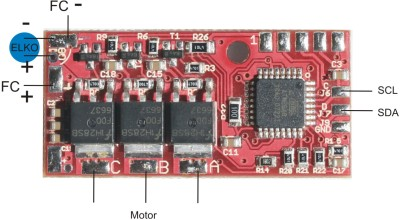
Assignment of the terminal
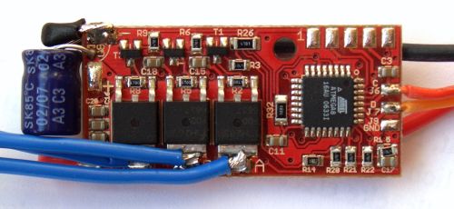
On the pre-assembled BL-Ctrl V1.2 you need to solder the enclosed Elko:

It is advisable to bend the capacitor by 90° so that it fit parallel to the outer side of the board.
Further you can see on the picture how to connect the I2C-Bus-Wires and the power supply.
![]() The controller is still sensitive to moisture and should be shrink wrapped with shrink tubing! For details see also BrushlessCtrl and water landing.
The controller is still sensitive to moisture and should be shrink wrapped with shrink tubing! For details see also BrushlessCtrl and water landing.
Flying with 4S LiPo
It is also possible and the same as with the BL-Ctrl V.1.1 to fly the MK with four-cell !Lipo's. See also 4S-LiPos.
Here you need to adjust the wirering in that way that the BL-Ctrl are hooked up directly to the power supply and not over the switch of the Flight-Ctrl. That is necessary because the switch is not designed for those current and starting flashes coming with the high voltage.
Schematic
(click for high resolution)
Please note: In version 1.2 for T1-3 the part PDTC143 with integrated base resistor is used. The base resistors R3, R6 and R9 need to be changed through a low-resistance resistor, i.e. 100 Ohm.
Troubleshooting
If the BL-Ctrl have a fault, you can see this e.g. on the flashing red LED on the BL-Ctrl.
How to find and fix a fault on this BL-Ctrl you can see here: Troubleshooting
Controlling with own Hardware
Controlling the BL-Ctrl with own hardware is easy.
AVR (plain)
A sample code for nearly any AVR is given below. The code will spin up the selected motor with a given speed. This is just to give an idea on how to interface them.
   1 #include <avr/io.h>
   2 #include <stdint.h>
   3 #include <util/delay.h>
   4 // using I²C Master library from
   5 // Peter Fleury ( http://jump.to/fleury )
   6 #include "i2cmaster.h"
   7
   8 #define TWI_BLCTRL_BASEADDR 0x52
   9
  10 int main(void) {
  11     i2c_init();
  12     uint8_t motor = 0; // 0 -> Motor1, 1 -> Motor2 etc...
  13         uint8_t speed = 10;
  14     uint8_t ret;
  15     while (1) {
  16         ret = i2c_start(TWI_BLCTRL_BASEADDR + (motor << 1) + I2C_WRITE);
  17         if (ret) {
  18                         // release bus
  19             i2c_stop();
  20                         // failed... maybe print error or something
  21         } else {
  22             i2c_write(speed);
  23             i2c_stop();
  24         }
  25         _delay_ms(50);
  26     }
  27 }
Arduino
A sample code for Arduino compatible devices is given below. The code will spin up the selected motor with a given speed. This is just to give an idea on how to interface them.
   1 #include <Wire.h>
   2
   3 void setup() {
   4     Wire.begin();
   5 }
   6
   7 #define TWI_BLCTRL_BASEADDR 0x52
   8
   9 void loop() {
  10
  11     int motor = 0; // 0 -> Motor1, 1 -> Motor2 etc...
  12     int speed = 10;
  13
  14     // The Wire library uses 7 bit addresses throughout. If you have a
  15     // datasheet or sample code that uses 8 bit address, you'll want to
  16     // drop the low bit (i.e. shift the value one bit to the right),
  17     // yielding an address between 0 and 127.
  18     Wire.beginTransmission((TWI_BLCTRL_BASEADDR + (motor << 1)) >> 1);
  19     Wire.write(speed);
  20     Wire.endTransmission();
  21
  22     delay(50);
  23 }
- KategorieMK-Baugruppe/de


